Portenta Mid Carrier User Manual
Learn about the hardware and software features of the Arduino® Portenta Mid Carrier.
Overview
The user manual comprehensively explains the Arduino Portenta Mid Carrier, compiling all its features in one place for easy accessibility. It includes instructions for setting up, testing, and using its various onboard functions.
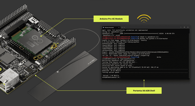
This manual can help users deploy the Portenta Mid Carrier industrial prototyping, swift development of machine vision applications, control systems for active mechanical designs, and many more applications.
Hardware and Software Requirements
Hardware Requirements
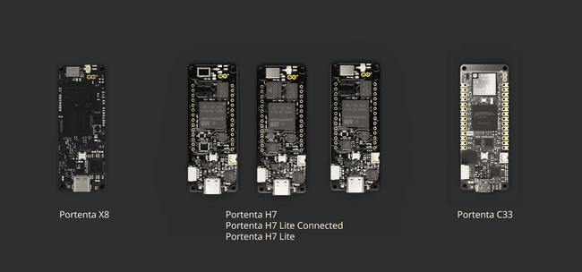
The Portenta Mid Carrier requires one of the SOM boards from the Portenta Family for operation:
The following accessories are needed:
- USB-C® cable (either USB-C® to USB-A or USB-C® to USB-C®) (x1)
- Wi-Fi® Access Point or Ethernet with Internet access (x1)
- Compatible antennas like the Arduino Pro 4G Module Antennas Kit (x1)
- Power cables: Wires with a cross-sectional area ranging from 0.82 mm² to 1.3 mm², corresponding to AWG sizes 18 to 16
Software Requirements
To use the Portenta Mid Carrier with a Portenta X8, please follow these guidelines:
- Ensure your Portenta X8 has the latest Linux image. Check this section of Portenta X8's user manual to verify that your Portenta X8 is up-to-date.
For the smooth functioning of the Portenta Mid Carrier with the Portenta X8, it is crucial to have at least Linux image version > 746 on the Portenta X8. To update your board to the latest image, use the Portenta X8 Out-of-the-box method or manually flash it, downloading the most recent version from this link.
To enter Flashing Mode with the Portenta X8 and the Portenta Mid Carrier, please consult the BOOT DIP switch configuration instructions within the present user manual.
- You will need Arduino IDE 1.8.10+, Arduino IDE 2.0+, or the Arduino Web Editor if you plan to run Arduino code on the auxiliary microcontroller of the Portenta X8.
For using the Portenta Mid Carrier with a Portenta H7/C33:
- The Arduino IDE 1.8.10+, Arduino IDE 2.0+, or Arduino Web Editor is needed to use the Portenta H7/C33 to run the Arduino code.
Product Overview
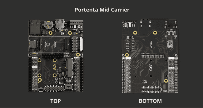
The Portenta Mid Carrier enhances the functionality of the Portenta family boards by providing a user-friendly platform for rapid prototyping. Designed for versatility, the carrier is fully compatible with all the Portenta SOM, making it a robust choice for a wide array of development and prototyping applications. It conveniently brings all high-density signals within reach through dedicated headers.
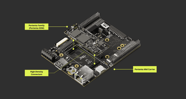
This carrier provides access to various peripherals. It highlights a Mini PCIe connector for Cat.4 cellular modules, suitable for solutions requiring extensive network coverage. It also includes two CAN lines, Ethernet, microSD, USB, camera connectors for DVP and MIPI interfaces, and a Display Serial Interface (DSI) compatible with GIGA Display Shield. Additionally, it features dedicated debug pins and an RTC battery backup, further enhancing the development experience by simplifying processes.
Carrier Architecture Overview
The Portenta Mid Carrier is designed for the Portenta family of SOM boards and offers a versatile range of power supply options:
- Power input of 5.0 V via the screw terminal
- Power through USB-C® connection on Portenta SOM
Its extensive connectivity features include a USB-A port for peripheral devices, 1000 Mbit Base-T Ethernet, and various interfaces like SPI, I2C, I2S, and UART accessible through a dedicated male header. It also supports MIPI and ArduCam® camera connections. The MIPI connector is specifically designed for the Portenta X8.
The carrier integrates a microSD slot for data logging purposes. It has dedicated headers for diverse interface options, JTAG pins for debugging purposes, and a mini PCIe connector for Cat.4 cellular modules. The CAN bus can be used either via an onboard or external transceiver.
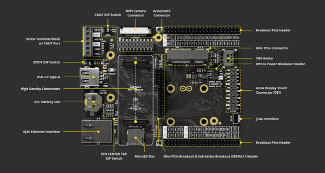
The Portenta Mid Carrier has the following characteristics:
Compatible SOM boards: The carrier is compatible with the Portenta X8 (ABX00049), Portenta H7 (ABX00042/ABX00045/ABX00046) and Portenta C33 (ABX00074).
Power management: The board can be powered up from different sources. The onboard screw terminal block allows a 5.0 V power supply to power the Portenta board, the carrier, and a mini PCIe module, if available.
The USB-C® interface of the Portenta X8, H7, and C33 can supply the needed power to the board when a 4G Module is not connected. It will require a 5.0 V external power source when operating mPCIe modules to guarantee a consistent power supply for the Portenta SOM and its carrier.
The 5.0 V pin from the carrier's breakout male header can also power the board. The carrier can deliver a maximum current of 2.0 A and therefore wires of at least 0.82 mm2 / 18 AWG are recommended.
USB connectivity: A USB-A female connector is used for data logging and supports 2.0 standard rates.
Communication: The carrier supports Ethernet interface (X1) via RJ45 connector 1000 MBase-T connected to High-Density pins.
The SPI (X2), I2C (x3), I2S (x1), and UART (x4) are accessible via dedicated breakout male header connectors (J14 - J15).
Two CAN bus ports are available, and CAN1 has an onboard transceiver controlled via CAN1 DIP switch (SW2). The CAN0 bus can be used with an external transceiver. CAN0 and CAN1 are available via the breakout pins header.
The MIPI interface (high-speed differential serial interface) is compatible only with the Portenta X8. Examples of supported devices include the OmniVision OV5647 and the Sony IMX219 sensors. For Portenta MCU SOM, the ArduCam® connector is also available, providing a Display Video Port (DVP) parallel interface.
Storage: The board has a microSD card slot and a USB-A female connector for data logging operation purposes.
Ethernet connectivity: The carrier offers a Gigabit Ethernet interface through an RJ45 connector 1000 MBase-T. The Ethernet properties can be configured with a dedicated 4-way DIP switch. More information can be found in the DIP switch configuration section.
Mini PCIe Connector: The carrier has a mini PCIe (Peripheral Component Interconnect Express) connector, i.e., an expansion card interface for modules compatible with its standard, such as Cat.4 modems as Arduino Pro 4G Modules.
PCIe Breakout Header: Besides the standard breakout header, the carrier also features a specific PCIe breakout header. This header provides access to each pin, enabling manual probing or the creation of external extensions for prototyping purposes.
GIGA Display Shield Connector: The Portenta Mid Carrier features a Display Serial Interface (DSI), which matches the Mobile Industry Processor Interface (MIPI) specifications, allowing it to connect displays that support MIPI DSI signals through its MIPI/DSI connector.
The GIGA Display Shield is compatible with the Portenta Mid Carrier. It is connected through the MIPI/DSI connector found on the carrier. This setup supports widely used frameworks like LVGL and GFX, enhancing its utility for various display applications.
Breakout Header: The carrier eases access to all the high-density pins on the Portenta boards. It makes all pins associated with communication protocols, buses, and GPIOs easily accessible for various applications.
Screw terminal block: The terminal block allows power supply line feed for the carrier and bus ports. It consists of VIN 5.0 VDC (x1), VCC 3.3 V (x1), CANH (CAN1) (x1), CANL (CAN1) (x1), and GND (x2).
Debug interface: The carrier features an onboard 10x pin 1.27mm JTAG connector.
DIP switch: The carrier features different DIP switches, allowing for different profiles for dedicated features or functionalities. The DIP switches are ETH CENTER TAP, BOOT, and CAN1. More information can be found in the DIP switch configuration section.
Carrier Topology
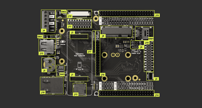
| Item | Onboard modules |
|---|---|
| J1 - J2 | High-Density connectors for Portenta boards |
| J3 | JTAG Interface |
| J4 | Screw Terminal Block with Onboard CAN Bus (CAN1) Transceiver |
| J5 | RTC Li-Po battery slot |
| J8 | Mini PCIe (Peripheral Component Interconnect Express) connector - (CELL Modules) |
| J9 | Mini PCI Express Power breakout header |
| J10 | MIPI camera connector - exclusive for Portenta X8 |
| J11 | ArduCam® connector |
| J12 | MicroSD slot for data logging operations |
| J13 | USB-A female connector |
| J14 - J15 | Breakout headers |
| J16 | Mini PCI Express Breakout Header |
| J17 | Sub-series of Mini PCI Express Breakout Header |
| J18 | Gigabit Ethernet connector - RJ45 |
| J19 | GIGA Display Shield connector (DSI) |
| SIM1 | Dedicated PCIe SIM Slot |
| SW1 | BOOT DIP Switch |
| SW2 | CAN Bus - CAN1 - DIP Switch |
| SW3 | ETH CENTER TAP DIP Switch |
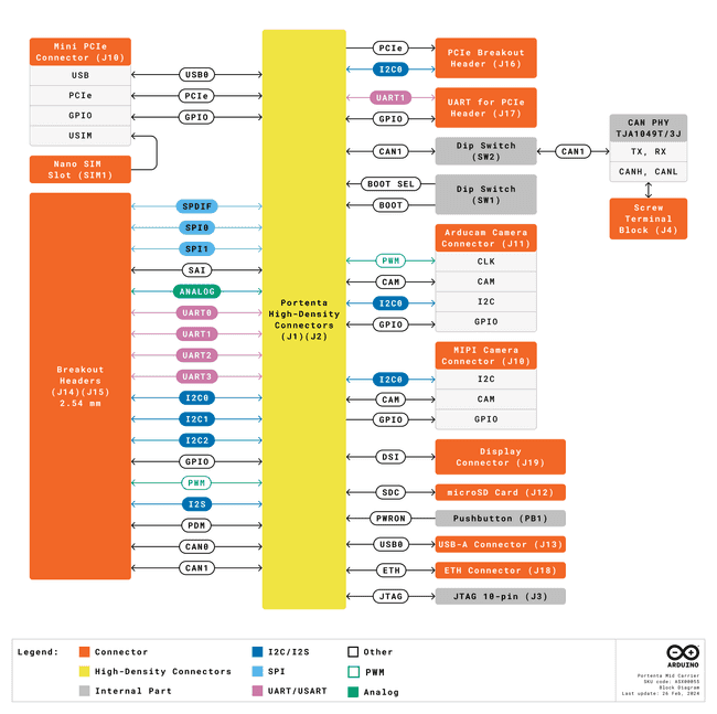
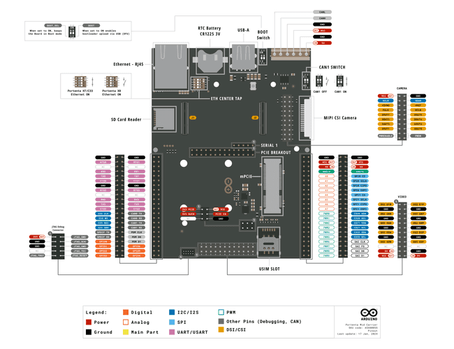
Pinout
Datasheet
The complete datasheet is available and downloadable as PDF from the link below:
Schematics
The complete schematics are available and downloadable as PDF from the link below:
STEP Files
The complete STEP files are available and downloadable from the link below:
Mechanical Information
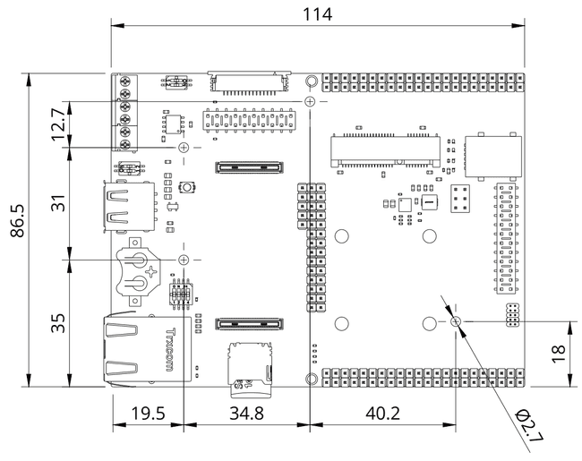
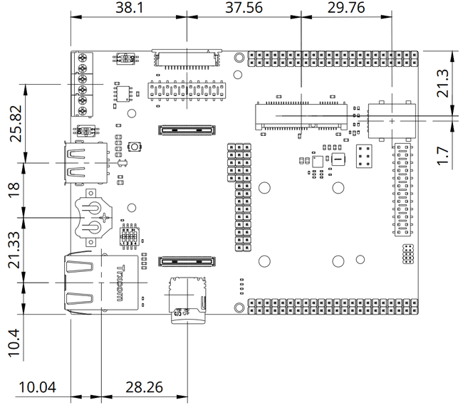
In this section, you can find mechanical information about the Portenta Mid Carrier. The board's dimensions are all specified here, within top and bottom views, including the placements of the components onboard.
Suppose you desire to design and manufacture a custom mounting device or create a custom enclosure for your carrier. In that case, the following image shows the dimensions for the mounting holes and general board layout. The given dimensions are all in millimeters [mm].
You can also access the STEP files, available here.
For reference, the following diagram outlines the dimensions measured between the connectors.
First Use Of Your Portenta Mid Carrier
Stack The Carrier
The design of the Portenta Mid Carrier enables effortless stacking of your preferred Portenta board.
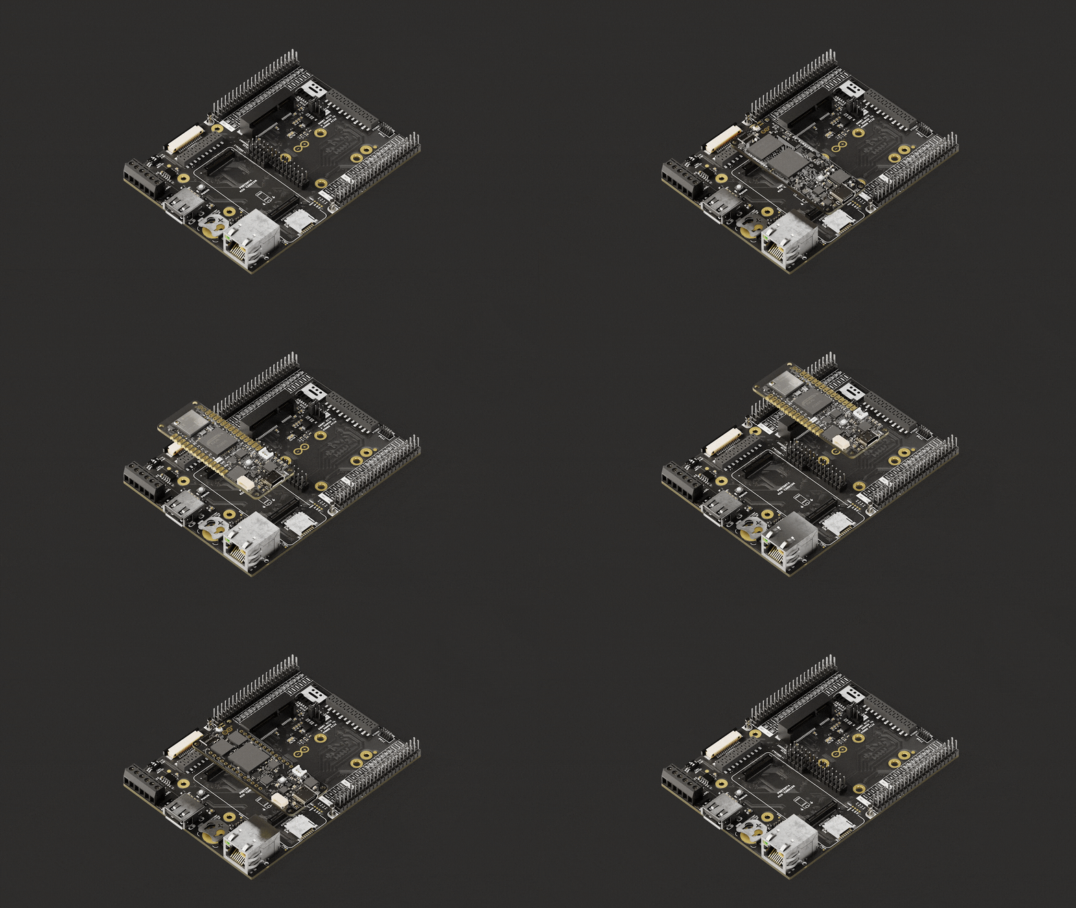
The illustration below demonstrates the pairing of the Portenta Mid Carrier with Portenta boards via High-Density connectors.

Once the Portenta is mounted on the carrier, you can power the carrier and begin prototyping.
Power The Board
The Portenta Mid Carrier offers several options for power supply:
The most recommended method is using an external 5.0 V power supply connected to the VIN pin on the screw terminal block of the board. This approach ensures that the Portenta Mid Carrier, the SOM (System on Module), and any connected PCIe modules are adequately powered.
To ensure the power demands are met, especially for the PMIC modules' external power, we recommend using cables that conform to appropriate electrical standards, such as ASTM B 258 standard, and can carry currents up to 2.0 A. Cables with a cross-sectional area ranging from 0.82 mm² to 1.3 mm², corresponding to AWG 18-16, should be adequate to manage 2.0 A of current.
For detailed information about connection points, please refer to the board pinout section in the user manual. It is essential to ensure that the current provided meets the requirements of all components, as specified in the operating conditions table provided later.
An external 5.0 V power supply can also be used, connected to the 5.0 V pin on the dedicated breakout header.
This method can power the Portenta Mid Carrier, the SOM, and any connected PCIe modules.
For further information on this type of connection, consult the board pinout section in the user manual. Ensure the power supply’s maximum current adheres to the specifications of all components.
Using a USB-C® cable (not included) connected to the Portenta core board of your choice (like the Portenta X8, H7, or C33) also powers the selected core board and the Portenta Mid Carrier. When a mPCIe module is attached, a 5.0 V external power source will be needed to ensure all connected boards receive a steady power supply.
The Portenta Mid Carrier can deliver a maximum current of 2.0 A.
The following diagram provides an overview of the power connection options available on the Portenta Mid Carrier, illustrating the different ways it can be powered:
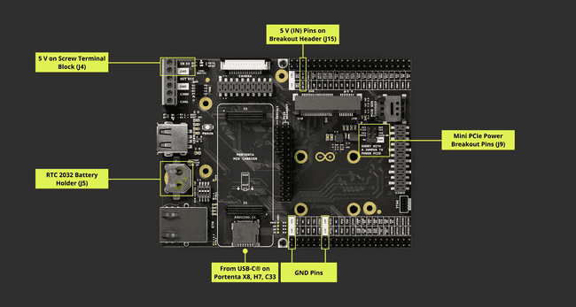
Please use a 5.0 V external power source when using an Arduino Pro 4G Module (EMEA / GNSS Global) or any other mPCIe modules due to their high power consumption. This is important for maintaining a stable power supply to the Portenta SOM and the carrier, particularly for extended periods of use.
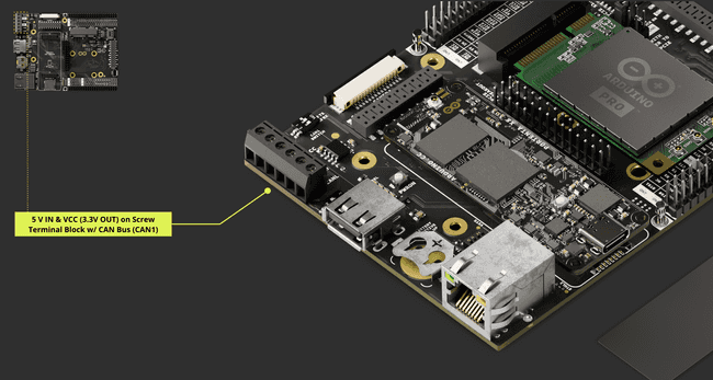
The image below focuses on the terminal block area of the Portenta Mid Carrier. This close-up view highlights the specific position for connecting the 5 V power sources within the terminal block:
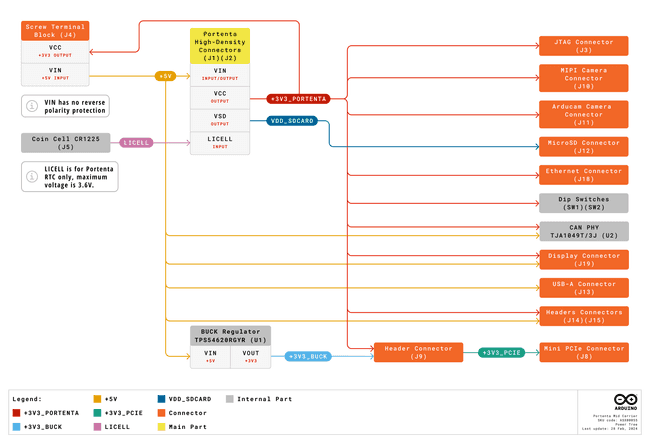
Refer to the power tree diagram to understand how power is distributed within the Portenta Mid Carrier. This diagram visually represents the allocation of power resources within the carrier:
Recommended Operating Conditions
To ensure the safety and longevity of the board, it is important to be aware of the Portenta Mid Carrier's operating conditions. The table provided below outlines the recommended operating conditions for the carrier:
| Parameter | Min | Typ | Max | Unit |
|---|---|---|---|---|
| 5.0 V from onboard screw terminal* of the Carrier | - | 5.0 | - | V |
| USB-C® input from the connected Portenta family board | - | 5.0 | - | V |
| +5 VDC from the carrier's onboard Breakout header | - | 5.0 | - | V |
| Current supplied by the carrier | - | - | 2.0 | A |
| Ambient operating temperature | -40 | - | 85 | °C |
The onboard screw terminal powers both the carrier and the connected Portenta board.
To ensure the power demands are met, and connectivity is reliable, especially for the PMIC modules' external power, we recommend using cables that conform to the appropriate electrical standards, such as ASTM B 258 standard and can carry currents up to 2.0 A. Cables with a cross-sectional area ranging from 0.82 mm² to 1.3 mm², corresponding to AWG 18-16, should be adequate to manage 2.0 A of current.
Carrier Characteristics Highlight
The Portenta Mid Carrier's functionality varies depending on which Portenta family board it is paired with. The table below outlines these differences:
| Features | Portenta X8 | Portenta H7 | Portenta C33 |
|---|---|---|---|
| MIPI Camera | Compatible | - | - |
| ArduCam® | - | Available | Available |
| GIGA Display Shield | - | Compatible (Touchscreen Enabled w/ External Pins) | - |
| Ethernet | 1 Gbit | 10/100 Mbit | 10/100 Mbit |
| JTAG Debug | Available | Available | Available |
| Storage Expansion | MicroSD slot | MicroSD slot | MicroSD slot |
| Mini PCIe Slot | Available | Available | Available |
| CAN FD (CAN1 - Onboard Transceiver) | Available | Available | Available |
| CAN FD (CAN0 - External Transceiver) | Available | - | Available |
| USB-A Support | Available | Available | Available |
This table provides a quick overview of the Portenta Mid Carrier's performance when paired with different Portenta boards. Each feature will be detailed in the subsequent section, and a guide on properly connecting the Portenta boards will be provided.
Hello World Carrier
Hello World Using Linux
Using Portenta X8 with Linux
To effectively use the Portenta Mid Carrier with the Portenta X8, align the High-Density connectors and the USB-C® port facing outside the carrier. The accompanying diagrams illustrate how to stack the board onto the carrier.
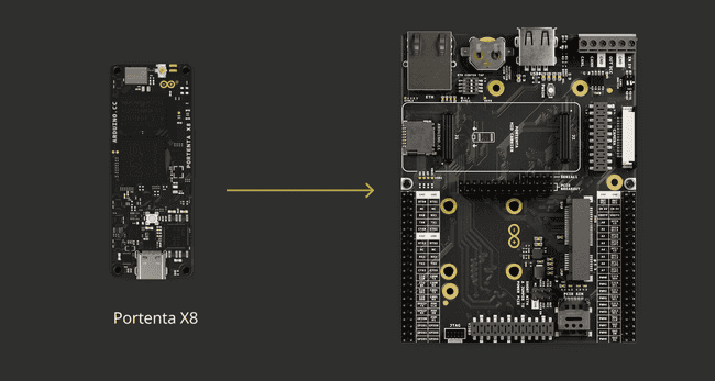
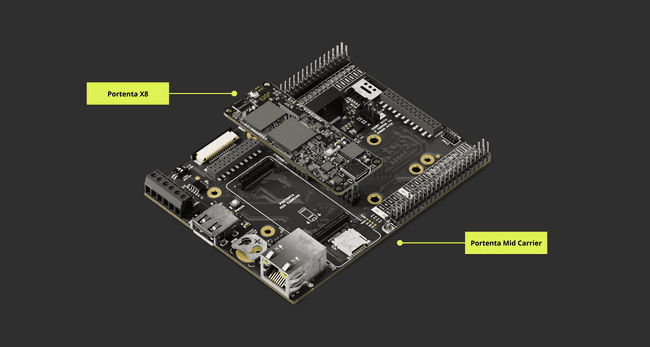
For optimal operation of the Portenta Mid Carrier with the Portenta X8, ensure you have at least version > 746 of the Linux image on the Portenta X8. The latest version can be downloaded [here]](https://downloads.arduino.cc/portentax8image/image-latest.tar.gz).
Hello World With Portenta X8 Shell
To verify the correct functioning of the Portenta Mid Carrier with the Portenta X8, we will use several Hello World examples with different approaches. These examples use Linux commands, Python® scripts, and the Arduino IDE to demonstrate various debugging methods and provide a basic introduction.
Starting with a Hello World example using Linux commands, we control GPIO through the Portenta X8's shell. Instructions for connecting to the Portenta X8 shell can be found here.
The commands below will help you set and control GPIO3, which can be linked to an LED or similar accessory.
Access the Portenta X8's shell using:
1adb shell2sudo su -Upon executing the
sudo su -The default password is fio
These grants root user access and the corresponding environment settings like
$HOME$PATH.These commands provide elevated access to the Portenta X8's shell, enabling system configuration changes that require administrative rights.
Use the following command to activate the GPIO device in
/sys/class/1echo 163 > /sys/class/gpio/exportCheck available GPIO elements with:
1ls /sys/class/gpioThis lists all initialized GPIOs. To view details of GPIO 163 (or GPIO3), use:
1ls /sys/class/gpio/gpio163Once the GPIO3 elements are exported, configure the GPIO using this command to set the I/O state of the pin. It can be set as Input (
inout1echo <I/O> >/sys/class/gpio/gpio163/directionFor our example, we set the pin as Output:
1echo out >/sys/class/gpio/gpio163/directionTo confirm the pin's setting, use:
1cat /sys/class/gpio/gpio163/directionAfter setting the GPIO as an output, control its state by setting it to High or Low.
To set the pin to HIGH:
1echo 1 >/sys/class/gpio/gpio163/valueTo set the pin to LOW:
1echo 0 >/sys/class/gpio/gpio163/valueTo stop controlling the GPIO, you can use the following command to unexport it, ensuring it no longer appears in the userspace:
1echo 163 >/sys/class/gpio/unexportTo confirm that the specified GPIO has been properly unexported, you can use the following command:
1ls /sys/class/gpioThis step helps you to prevent unintentional modifications to the GPIO element configuration.
Hello World Using Linux and Python® Scripts
Instead of manually toggling the GPIO3 on the Portenta X8 via the command line, we can use a Python® script for automation and extended control logic.
Here is a compatible script for the ADB shell on the Portenta X8:
1#!/usr/bin/env python32import time3
4class GPIOController:5 def __init__(self, gpio_number):6 self.gpio_number = gpio_number7 self.gpio_path = f"/sys/class/gpio/gpio{gpio_number}/"8
9 def export(self):10 with open("/sys/class/gpio/export", "w") as f:11 f.write(str(self.gpio_number))12
13 def unexport(self):14 with open("/sys/class/gpio/unexport", "w") as f:15 f.write(str(self.gpio_number))16
17 def set_direction(self, direction):18 with open(f"{self.gpio_path}direction", "w") as f:19 f.write(direction)20
21 def read_direction(self):22 with open(f"{self.gpio_path}direction", "r") as f:23 return f.read().strip()24
25 def set_value(self, value):26 with open(f"{self.gpio_path}value", "w") as f:27 f.write(str(value))28
29 def read_value(self):30 with open(f"{self.gpio_path}value", "r") as f:31 return int(f.read().strip())32
33def main():34 print("============================================")35 print("Hello World!")36 print("============================================")37
38 gpio = GPIOController(163)39
40 # Export GPIO41 gpio.export()42
43 # Set as output44 gpio.set_direction("out")45 if gpio.read_direction() == "out":46 print("GPIO set as output.")47 print("GPIO3 blinking 20 times")48
49
50 # Turn on (set to 1) and then off (set to 0)51 for i in range(1,20,1):52 gpio.set_value(1)53 time.sleep(1)54 gpio.set_value(0)55 time.sleep(1)56
57
58 print("GPIO Unexport")59 gpio.unexport()60 print("End of the program")61 exit()62
63if __name__ == "__main__":64 main()The script can be named
hello_world_python.py1adb push hello_world_python.py /home/fioThis uploads the file to the
/home/fio1cd /home/fioUse the following command to run the script:
1python3 hello_world_python.pyWhen the script runs, the Portenta Mid Carrier's GPIO3 will begin to toggle its state.
For more information on how the board operates and to maximize its use with the Portenta Mid Carrier, refer to the Portenta X8 user manual.
The Portenta X8 works in a Linux environment based on the Yocto Linux distribution. It is recommendable to read how the Portenta X8 works in terms of Linux environment here.
Hello World Using Arduino
Using Portenta X8 / H7 / C33 with Arduino
The Portenta X8 can also operate within the Arduino environment and retains the same hardware setup as explained here. It can become a handy tool when opting for the Remote Procedure Call (RPC) mechanism within development. You can find more information on RPC in the "Data Exchange Between Python® on Linux & Arduino Sketch" tutorial.
The Portenta H7 and C33 boards have hardware setups identical to the Portenta X8. To mount them on the Mid Carrier, please align the High-Density connectors along with the USB-C® port orientation facing outside the carrier.
The diagrams below show how the Portenta H7 and C33 stack on the carrier:
- Portenta H7
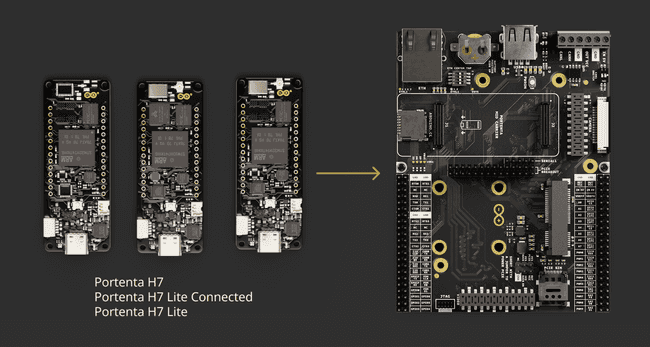
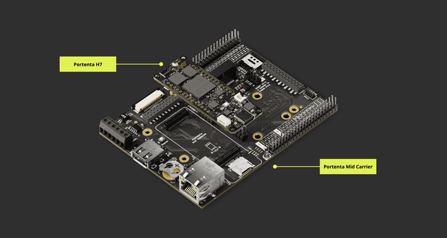
- Portenta C33
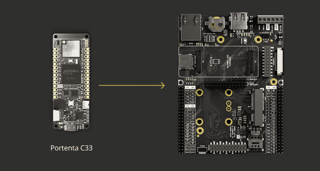
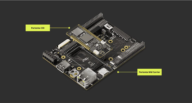
Hello World With Arduino
In this section, you will learn how to use the Portenta X8, Portenta H7, or Portenta C33 with the Portenta Mid Carrier. You will interact with the GPIO3 pin within the Arduino environment.
Upon connecting a compatible Portenta board to the Portenta Mid Carrier, launch the Arduino IDE and set up the following code:
1// the setup function runs once when you press reset or power the board2void setup() {3 // Initialize the digital pin of the chosen SOM as an output4 pinMode(<DIGITAL_PIN>, OUTPUT);5}6
7// the loop function runs over and over again forever8void loop() {9 digitalWrite(<DIGITAL_PIN>, HIGH); // turn the select pin on (HIGH is the voltage level)10 delay(1000); // wait for a second11 digitalWrite(<DIGITAL_PIN>, LOW); // turn the select pin off by making the voltage LOW12 delay(1000); // wait for a second13}Make sure to substitute
<DIGITAL_PIN>- Portenta X8: PF_4
- Portenta H7: PD_5
- Portenta C33: 30
For instance, with the Portenta X8, the script will be:
1// the setup function runs once when you press reset or power the board2void setup() {3 // Initialize the digital pin of the chosen SOM as an output4 pinMode(PF_4, OUTPUT);5}6
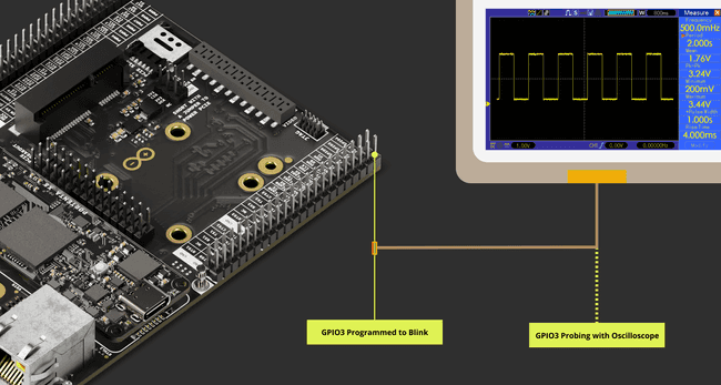
7// the loop function runs over and over again forever8void loop() {9 digitalWrite(PF_4, HIGH); // turn the select pin on (HIGH is the voltage level)10 delay(1000); // wait for a second11 digitalWrite(PF_4, LOW); // turn the select pin off by making the voltage LOW12 delay(1000); // wait for a second13}Upon uploading the sketch to the board, GPIO3 will be driven to switch its state. The image below shows the anticipated outcome if an oscilloscope probe is connected to GPIO3, exemplifying a blinking LED or any actuator that imitates signal switching.
Please check out the following documentation below to better understand each board and optimize its use with the Portenta Mid Carrier:
- Portenta C33 user manual.
- Portenta H7 set-up guide.
- Portenta X8 user manual. Additionally, here is a tutorial for a detailed guide on uploading sketches to the M4 Core on Arduino Portenta X8.
Carrier Features and Interfaces
The carrier presents various features and interfaces to meet needs and applications. This section summarizes the key hardware interfaces, storage alternatives, and configuration methods incorporated into the carrier.
The following sub-sections offer a detailed examination of each feature's specifications, providing thorough information for the most effective use of the carrier.
Hardware Interfaces
The present sub-section delves into the fundamental hardware connection points and interfaces on the Portenta Mid Carrier. It covers a variety of components, from the mini PCIe interface to the connectors and camera interfaces.
High-Density Connectors
The Portenta X8, H7, and C33 models expand their capabilities using High-Density connectors. To fully grasp the functionality and layout of these connectors, it is recommended that you consult the detailed pinout documentation available for each Portenta model.
This documentation provides an in-depth view of the connectors, ensuring a comprehensive understanding of how they enhance the functionality of these devices.
- Complete Portenta X8 pinout information
- Complete Portenta H7 pinout information
- Complete Portenta C33 pinout information
Mini PCI Express Interface (J8)
Mini PCIe, short for Mini Peripheral Component Interconnect Express, is a compact version of the PCIe interface, predominantly used in laptops and small devices for adding functionalities like Wi-Fi®, Bluetooth®, and cellular modems.
These cards are significantly smaller than standard PCIe cards, typically measuring around 30 mm x 50.95 mm, and are designed to fit into the limited spaces of compact systems. They connect to a motherboard via a dedicated Mini PCIe slot, supporting PCIe and USB 2.0 interfaces. They are available in full-size and half-size variants.
In its portfolio, Arduino has two mini PCIe modules compatible with Portenta Mid Carrier, the Arduino Pro 4G Module, a Cat.4 modem mini PCIe card available in two variants: EMEA and GNSS Global.
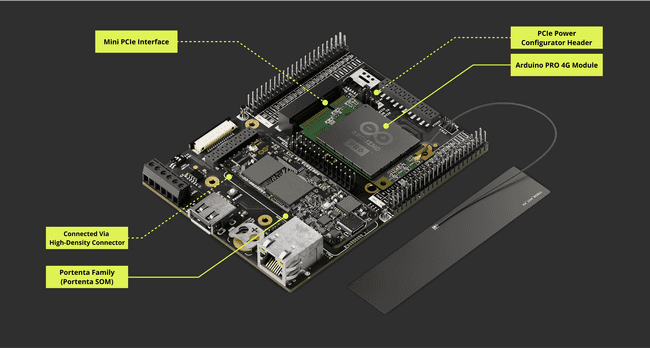
The onboard Mini PCIe slot of the Portenta Mid Carrier has the following pin layout:
| Pin Number | Silkscreen Pin | Power Net | Portenta Standard Pin | High-Density Pin | Pin Detail |
|---|---|---|---|---|---|
| 1 | N/A | Connected to pin 23 of J16 connector | |||
| 2 | N/A | +3V3 PCIE (Out) | From PCIE dedicated high current 3V3 power supply | ||
| 3 | N/A | Connected to pin 21 of J16 connector | |||
| 4 | N/A | Ground | GND | J1-22, J1-31, J1-42, J1-47, J1-54, J2-24, J2-33, J2-44, J2-57, J2-70 | |
| 5 | N/A | Connected to pin 19 of J16 connector | |||
| 6 | N/A | Connected to pin 17 of J16 connector | |||
| 7 | N/A | GPIO_1 | J2-48 | ||
| 8 | N/A | Connected to pin C1 of SIM1 slot | |||
| 9 | N/A | Ground | GND | J1-22, J1-31, J1-42, J1-47, J1-54, J2-24, J2-33, J2-44, J2-57, J2-70 | |
| 10 | N/A | Connected to pin C7 of SIM1 slot | |||
| 11 | N/A | PCIE_CK_N | J2-19 | ||
| 12 | N/A | Connected to pin C3 of SIM1 slot | |||
| 13 | N/A | PCIE_CK_P | J2-17 | ||
| 14 | N/A | Connected to pin C2 of SIM1 slot | |||
| 15 | N/A | Ground | GND | J1-22, J1-31, J1-42, J1-47, J1-54, J2-24, J2-33, J2-44, J2-57, J2-70 | |
| 16 | N/A | Connected to pin 15 of J16 connector | |||
| 17 | N/A | Connected to pin 13 of J16 connector | |||
| 18 | N/A | Ground | GND | J1-22, J1-31, J1-42, J1-47, J1-54, J2-24, J2-33, J2-44, J2-57, J2-70 | |
| 19 | N/A | Connected to pin 11 of J16 connector | |||
| 20 | N/A | GPIO_2 | J2-50 | ||
| 21 | N/A | Ground | GND | J1-22, J1-31, J1-42, J1-47, J1-54 J2-24, J2-33, J2-44, J2-57, J2-70 | |
| 22 | N/A | PCIE_RST | J2-21 | Connected to pin 9 of J16 connector | |
| 23 | N/A | PCIE_RX_N | J2-15 | ||
| 24 | N/A | +3V3 PCIE (Out) | From PCIE dedicated high current 3V3 power supply | ||
| 25 | N/A | PCIE_RX_P | J2-13 | ||
| 26 | N/A | Ground | GND | J1-22, J1-31, J1-42, J1-47, J1-54, J2-24, J2-33, J2-44, J2-57, J2-70 | |
| 27 | N/A | Ground | GND | J1-22, J1-31, J1-42, J1-47, J1-54, J2-24, J2-33, J2-44, J2-57, J2-70 | |
| 28 | N/A | Connected to pin 22 of J16 connector | |||
| 29 | N/A | Ground | GND | J1-22, J1-31, J1-42, J1-47, J1-54, J2-24, J2-33, J2-44, J2-57, J2-70 | |
| 30 | N/A | I2C0_SCL | J1-46 | Connected to pin 28 of J15 connector | |
| 31 | N/A | PCIE_TX_N | J2-11 | ||
| 32 | N/A | I2C0_SDA | J1-44 | Connected to pin 26 of J15 connector | |
| 33 | N/A | PCIE_TX_P | J2-9 | ||
| 34 | N/A | Ground | GND | J1-22, J1-31, J1-42, J1-47, J1-54, J2-24, J2-33, J2-44, J2-57, J2-70 | |
| 35 | N/A | Ground | GND | J1-22, J1-31, J1-42, J1-47, J1-54, J2-24, J2-33, J2-44, J2-57, J2-70 | |
| 36 | N/A | USB0_D_N | J1-28 | Connected to USB-A connector J13 | |
| 37 | N/A | Ground | GND | J1-22, J1-31, J1-42, J1-47, J1-54, J2-24, J2-33, J2-44, J2-57, J2-70 | |
| 38 | N/A | USB0_D_P | J1-26 | Connected to USB-A connector J13 | |
| 39 | N/A | +3V3 PCIE (Out) | From PCIE dedicated high current 3V3 power supply | ||
| 40 | N/A | Ground | GND | J1-22, J1-31, J1-42, J1-47, J1-54, J2-24, J2-33, J2-44, J2-57, J2-70 | |
| 41 | N/A | +3V3 PCIE (Out) | From PCIE dedicated high current 3V3 power supply | ||
| 42 | N/A | Connected to pin 20 of J16 connector | |||
| 43 | N/A | Ground | GND | J1-22, J1-31, J1-42, J1-47, J1-54, J2-24, J2-33, J2-44, J2-57, J2-70 | |
| 44 | N/A | Connected to pin 18 of J16 connector | |||
| 45 | N/A | Connected to pin 12 of J16 connector | |||
| 46 | N/A | Connected to pin 16 of J16 connector | |||
| 47 | N/A | Connected to pin 10 of J16 connector | |||
| 48 | N/A | Connected to pin 14 of J16 connector | |||
| 49 | N/A | Connected to pin 8 of J16 connector | |||
| 50 | N/A | Ground | GND | J1-22, J1-31, J1-42, J1-47, J1-54, J2-24, J2-33, J2-44, J2-57, J2-70 | |
| 51 | N/A | Connected to pin 6 of J16 connector | |||
| 52 | N/A | +3V3 PCIE (Out) | From PCIE dedicated high current 3V3 power supply |
Mini PCIe Power Breakout Header (J9)
The Mini PCIe slot of the Portenta Mid Carrier has a dedicated breakout pin to control the power distribution of its interface.
| Pin Number | Silkscreen Pin | Power Net | Portenta Standard Pin | High-Density Pin |
|---|---|---|---|---|
| 1 | 3V3 PCIE | +3V3 PCIE (Out) | ||
| 2 | VCC | +3V3 Portenta (Out) | ||
| 3 | 3V3 BUCK | +3V3 Buck (Out) | ||
| 4 | PCIE ENABLE | PCIE_EN | GPIO_5 | J2-56 |
| 5 | NC | NC | ||
| 6 | GND | Ground |
To accommodate the power requirements and ensure reliable connectivity, jumper cables with appropriate electrical standards, such as ASTM B 258 standard, should be used to support a current of up to 2A. Jumper cables with a cross-sectional area of 0.82 mm² to 1.3 mm² (approximately equivalent to AWG 18-16) should support 2.0 A of current.
This precaution is necessary to prevent wire overheating and ensure reliable power transmission for the connected Mini PCIe-compatible module, such as Cat.4 modems. A minimum requirement to set the mini PCIe interface with the Portenta Mid Carrier consists of:
- 3V3 PCIE pin connected to 3V3 BUCK pin
- Properly inserted mini PCIe module, e.g., Pro 4G GNSS Module Global / Pro 4G EMEA Module
Please use a 5.0 V external power source when using an Arduino Pro 4G Module (EMEA / GNSS Global) or any other mPCIe modules due to their high power consumption. This is important for maintaining a stable power supply to the Portenta SOM and the carrier, particularly for extended periods of use.
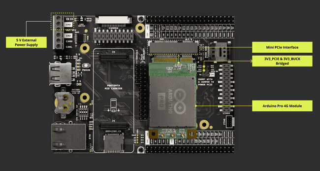
The following animation shows the assembly process using a mini PCIe slot compatible with the Pro 4G module.
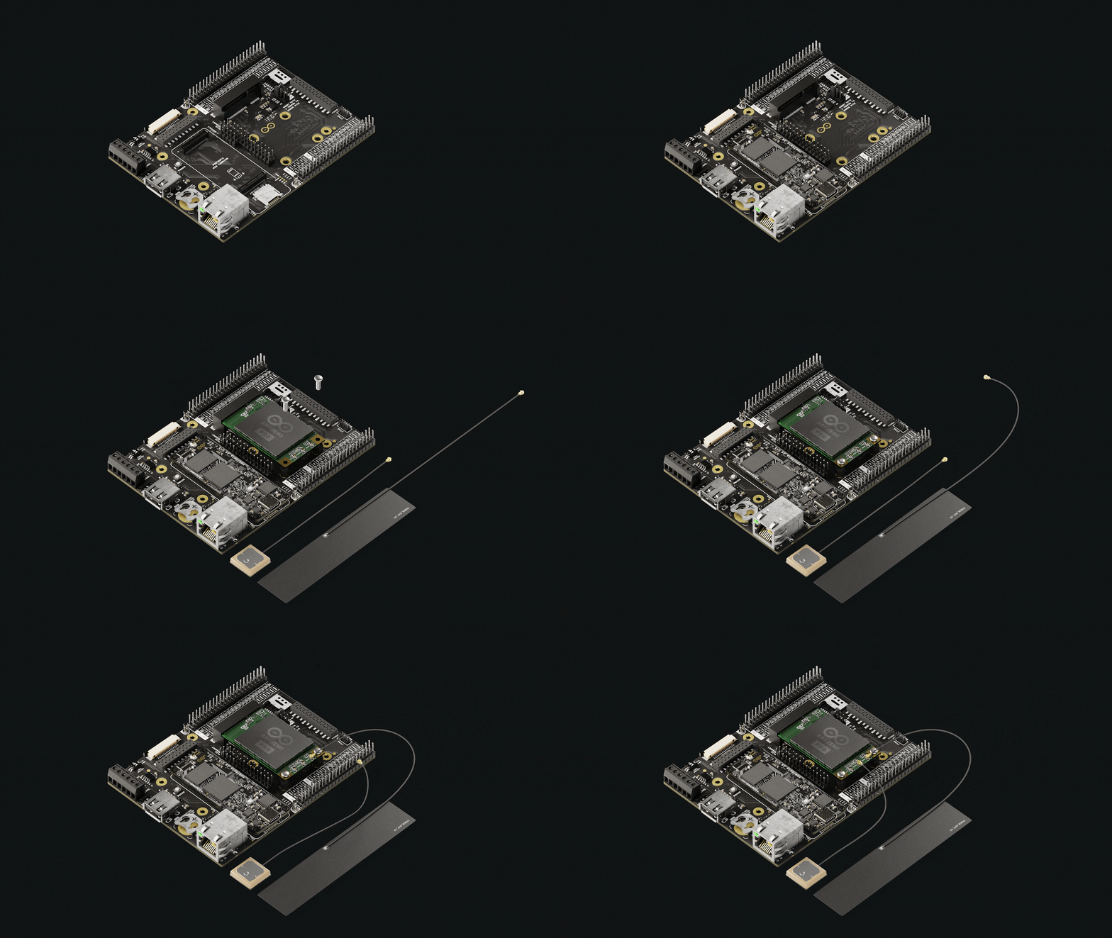
To immediately jump to the Pro 4G Module integration with the Portenta Mid Carrier, you can go to the Cat.4 Modem (Cellular Connectivity) subsection within the Network Connectivity section.
Accessing Mini PCIe Interface
It is possible to know if the compatible mini PCIe module has been correctly set up and detected using the Portenta X8. The Portenta Mid Carrier's mini PCIe lanes contain USB lines, and the Pro 4G Module is recognized as a USB module.
Thus, to verify that the Pro 4G Module has been correctly powered up and recognized by the Portenta X8 with the Portenta Mid Carrier, the following command is used instead of the
lspci1lsusbThe above command will list the devices that the Portenta X8 has recognized. The following image shows similar results if the Pro 4G Module is detected.
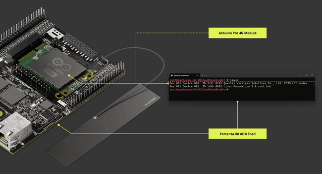
To learn about implementing the Pro 4G Module with the Portenta Mid Carrier immediately, you can jump to the Cat.4 Modem (Cellular Connectivity) section under the Network Connectivity section.
MIPI Camera Connector(J10)
The Portenta Mid Carrier integrates a dedicated camera connector, enabling the Portenta X8 to interface with MIPI cameras. However, it is important to note that the out-of-the-box Alpine shell does not support specific commands directly through the ADB shell.
In contrast, the Portenta H7 and C33 models do not support the MIPI interface and thus cannot use the camera connector.
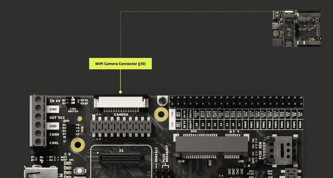
The MIPI connector's pin distribution is as follows:
| Pin number | Power Net | Portenta HD Standard Pin | High-Density Pin | Interface |
|---|---|---|---|---|
| 1 | GND | GND | J1-22, J1-31, J1-42, J1-47, J1-54, J2-24, J2-33, J2-44, J2-57, J2-70 | |
| 2 | CAM_D0_D0_N | J2-16 | ||
| 3 | CAM_D1_D0_P | J2-14 | ||
| 4 | GND | GND | J1-22, J1-31, J1-42, J1-47, J1-54, J2-24, J2-33, J2-44, J2-57, J2-70 | |
| 5 | CAM_D2_D1_N | J2-12 | ||
| 6 | CAM_D3_D1_P | J2-10 | ||
| 7 | GND | GND | J1-22, J1-31, J1-42, J1-47, J1-54, J2-24, J2-33, J2-44, J2-57, J2-70 | |
| 8 | CAM_CK_CK_N | J2-20 | ||
| 9 | CAM_VS_CK_P | J2-18 | ||
| 10 | GND | GND | J1-22, J1-31, J1-42, J1-47, J1-54, J2-24, J2-33, J2-44, J2-57, J2-70 | |
| 11 | GPIO_5 | J2-56 | ||
| 12 | NC | NC | ||
| 13 | I2C1_SCL | J1-45 | I2C 1 SCL | |
| 14 | I2C1_SDA | J1-43 | I2C 1 SDA | |
| 15 | +3V3_PORTENTA | VCC | J2-23, J2-34, J2-43, J2-69 |
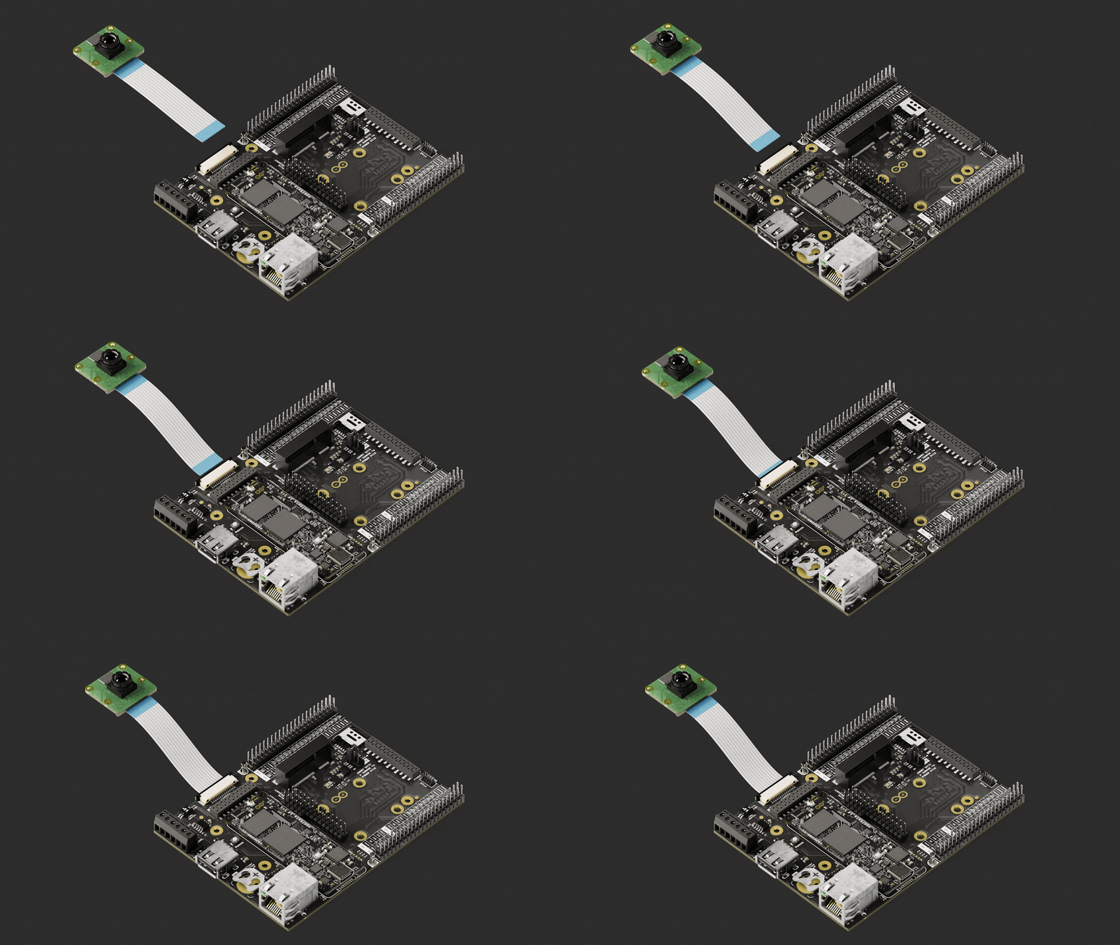
The Portenta Mid Carrier supports MIPI cameras when paired with the Portenta X8, allowing for a flexible connection to compatible cameras via a flex cable.
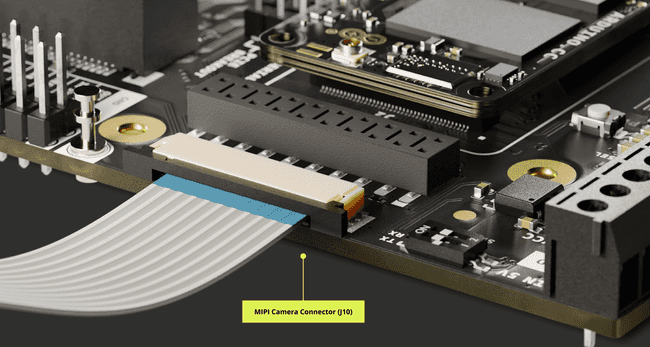
The following camera devices are compatible:
- OmniVision OV5647 sensor (Raspberry Pi® Camera Module 1)
- Sony IMX219 sensor (Raspberry Pi® Camera Module 2)
Using Linux
To initialize the Raspberry Pi Camera v1.3, based on the OV5647 CMOS sensor, follow these steps using the Portenta X8 environment, which will set environment variables and specify camera and board overlays:
1fw_setenv carrier_custom 11fw_setenv is_on_carrier yes1fw_setenv carrier_name mid1fw_setenv overlays 'ov_som_lbee5kl1dx ov_som_x8h7 ov_carrier_breakout_usbfs ov_carrier_mid_pcie_mini ov_carrier_mid_ov5647_camera_mipi'Then, you can consider proceeding to start the camera to capture beginning with the runtime directory definition for
Wayland1export XDG_RUNTIME_DIR=/run # location of wayland-0 socket2modprobe ov5647_mipiCheck the supported formats and controls of the connected video device:
1v4l2-ctl --list-formats-ext --device /dev/video02v4l2-ctl -d /dev/video0 --list-ctrlsCapture a single frame in JPEG format using GStreamer:
1export GST_DEBUG=32gst-top-1.0 gst-launch-1.0 -v v4l2src device=/dev/video0 num-buffers=1 ! "video/x-bayer, format=bggr, width=640, height=480, bpp=8, framerate=30/1" ! bayer2rgbneon reduce-bpp=t ! jpegenc ! filesink location=/tmp/test.jpgThis command allows to capture one frame and save the file as
/tmp/test.jpgGStreamer1gst-top-1.0 gst-launch-1.0 -v v4l2src device=/dev/video0 num-buffers=300 ! "video/x-bayer, format=bggr, width=640, height=480, bpp=8, framerate=30/1" ! bayer2rgbneon reduce-bpp=t ! queue ! waylandsinkFollowing these instructions, you can capture and stream video from the Raspberry Pi Camera v1.3 with the OV5647 sensor.
For improved image quality, consider using a MIPI camera module with an integrated Image Signal Processor (ISP).
ArduCam® Compatibility Via Camera Socket (J11)
The Portenta Mid Carrier is also characterized for compatibility with the ArduCam® via the Digital Video Port (DVP) interface. Its compatibility can go with HM01B0, HM0360, GC2145, or OV7675 modules.
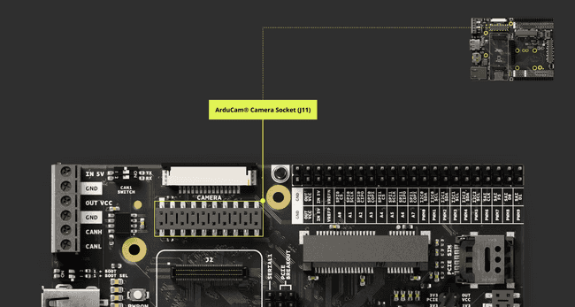
The connection is accomplished via the Camera socket (J11), and it is specified as follows:
| Pin Number | Silkscreen Pin | Power Net | Portenta Standard Pin | High-Density Pin |
|---|---|---|---|---|
| 1 | VCC | +3V3 Portenta (Out) | VCC | J2-23, J2-34, J2-43, J2-69 |
| 2 | GND | Ground | GND | J1-22, J1-31, J1-42, J1-47, J1-54, J2-24, J2-33, J2-44, J2-57, J2-70 |
| 3 | SCL0 | I2C0_SCL | J1-46 | |
| 4 | SDA0 | I2C0_SDA | J1-44 | |
| 5 | VSYNC | CAM_VS_CK_P | J2-18 | |
| 6 | HREF | CAM_HS | J2-22 | |
| 7 | PCLK | CAM_CK_CK_N | J2-20 | |
| 8 | XCLK | PWM_0 | J2-59 | |
| 9 | DOUT7 | CAM_D7_D3_P | J2-2 | |
| 10 | DOUT6 | CAM_D6_D3_N | J2-4 | |
| 11 | DOUT5 | CAM_D5_D2_P | J2-6 | |
| 12 | DOUT4 | CAM_D4_D2_N | J2-8 | |
| 13 | DOUT3 | CAM_D3_D1_P | J2-10 | |
| 14 | DOUT2 | CAM_D2_D1_N | J2-12 | |
| 15 | DOUT1 | CAM_D1_D0_P | J2-14 | |
| 16 | DOUT0 | CAM_D0_D0_N | J2-16 | |
| 17 | PWRENABLE | GPIO_3 | J2-52 | |
| 18 | PWDN | GPIO_4 | J2-54 | |
| 19 | PWRENABLE | GPIO_3 | J2-52 | |
| 20 | PWDN | GPIO_4 | J2-54 |
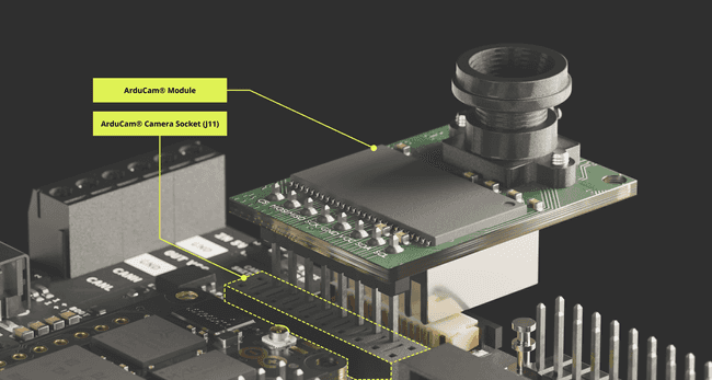
The following image shows the camera socket close-up of the Portenta Mid Carrier with an ArduCam® module that may be used to stack on the carrier.
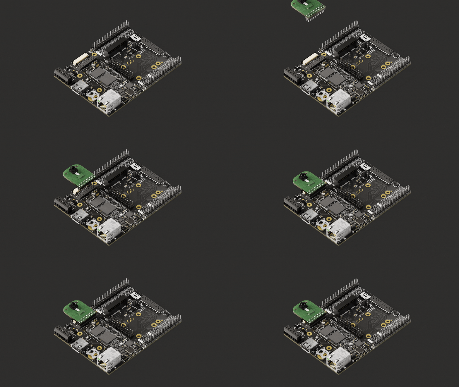
As well as the following clip shows Arducam-F Shield V2 Camera module shield with OV2640, which is compatible with the Portenta Mid Carrier when paired with the Portenta H7 and C33.
Using Arduino
The arducam_dvp library provides an example that supports three types of camera models: OV7670, Himax HM0360, Himax HM01B0, and GC2145. It captures pixel data and stores it in a frame buffer. These stored frames can subsequently be accessed continuously for further processing. It is compatible with the Portenta H7, and the CameraCaptureRawBytes example looks as follows:
1#include "arducam_dvp.h"2
3#define ARDUCAM_CAMERA_HM01B04
5#ifdef ARDUCAM_CAMERA_HM01B06 #include "Himax_HM01B0/himax.h"7 HM01B0 himax;8 Camera cam(himax);9 #define IMAGE_MODE CAMERA_GRAYSCALE10#elif defined(ARDUCAM_CAMERA_HM0360)11 #include "Himax_HM0360/hm0360.h"12 HM0360 himax;13 Camera cam(himax);14 #define IMAGE_MODE CAMERA_GRAYSCALE15#elif defined(ARDUCAM_CAMERA_OV767X)16 #include "OV7670/ov767x.h"17 // OV7670 ov767x;18 OV7675 ov767x;19 Camera cam(ov767x);20 #define IMAGE_MODE CAMERA_RGB56521#elif defined(ARDUCAM_CAMERA_GC2145)22 #include "GC2145/gc2145.h"23 GC2145 galaxyCore;24 Camera cam(galaxyCore);25 #define IMAGE_MODE CAMERA_RGB56526#endif27
28FrameBuffer fb;29
30void blinkLED(uint32_t count = 0xFFFFFFFF,uint32_t t_delay = 50)31{32 while (count--)33 {34 digitalWrite(LED_BUILTIN, LOW); // turn the LED on (HIGH is the voltage level)35 delay(t_delay); // wait for a second36 digitalWrite(LED_BUILTIN, HIGH); // turn the LED off by making the voltage LOW37 delay(t_delay); // wait for a second38 }39}40
41
42void setup()43{44 pinMode(LED_BUILTIN, OUTPUT);45 // Init the cam QVGA, 30FPS46 if (!cam.begin(CAMERA_R320x240, IMAGE_MODE, 30))47 {48 blinkLED();49 }50 blinkLED(5);51 Serial.begin(921600);52}53
54void loop()55{56 if(Serial.read() != 0x01)57 {58 blinkLED(1,10);59 return;60 }61 // Grab frame and write to serial62 if (cam.grabFrame(fb, 3000) == 0)63 {64 Serial.write(fb.getBuffer(), cam.frameSize());65 }66 else67 {68 blinkLED(20,100);69 delay(1000);70 }71}For the Portenta C33, given it has a different architecture, it is possible to navigate using the official ArduCam® source known as Arducam_Mega library.
GIGA Display Shield Connector (J19)
The Arduino GIGA Display Shield is an add-on that can be used with the Portenta Mid Carrier, offering an 800x480 display with touch support. The display shield can be connected via MIPI DSI (Display Serial Interface).
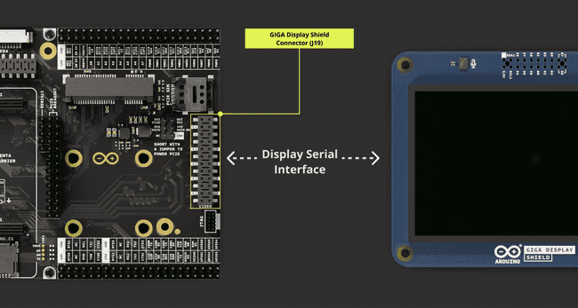
The shield also features a camera connector, built-in IMU, microphone, and an RGB pixel. The video display connector (J19) of the carrier is specified in the following table:
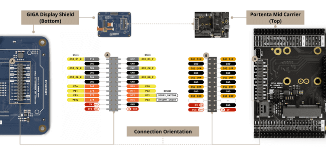
| Pin Number | Silkscreen Pin | Power Net | Portenta Standard Pin | High-Density Pin |
|---|---|---|---|---|
| 1 | DSI D1N | DSI_D1_N | J1-12 | |
| 2 | DSI D1P | DSI_D1_P | J1-10 | |
| 3 | GND | Ground | GND | J1-22, J1-31, J1-42, J1-47, J1-54, J2-24, J2-33, J2-44, J2-57, J2-70 |
| 4 | GND | Ground | GND | J1-22, J1-31, J1-42, J1-47, J1-54, J2-24, J2-33, J2-44, J2-57, J2-70 |
| 5 | DSI CKN | DSI_CK_N | J1-20 | |
| 6 | DSI CKP | DSI_CK_P | J1-18 | |
| 7 | GND | Ground | GND | J1-22, J1-31, J1-42, J1-47, J1-54, J2-24, J2-33, J2-44, J2-57, J2-70 |
| 8 | GND | Ground | GND | J1-22, J1-31, J1-42, J1-47, J1-54, J2-24, J2-33, J2-44, J2-57, J2-70 |
| 9 | DSI D0N | DSI_D0_N | J1-16 | |
| 10 | DSI D0P | DSI_D0_P | J1-14 | |
| 11 | GND | Ground | GND | J1-22, J1-31, J1-42, J1-47, J1-54, J2-24, J2-33, J2-44, J2-57, J2-70 |
| 12 | GND | Ground | GND | J1-22, J1-31, J1-42, J1-47, J1-54, J2-24, J2-33, J2-44, J2-57, J2-70 |
| 13 | DSI D2N | DSI_D2_N | J1-8 | |
| 14 | DSI D2P | DSI_D2_P | J1-6 | |
| 15 | GND | Ground | GND | J1-22, J1-31, J1-42, J1-47, J1-54, J2-24, J2-33, J2-44, J2-57, J2-70 |
| 16 | GND | Ground | GND | J1-22, J1-31, J1-42, J1-47, J1-54, J2-24, J2-33, J2-44, J2-57, J2-70 |
| 17 | DSI D3N | DSI_D3_N | J1-4 | |
| 18 | DSI D3P | DSI_D3_P | J1-2 | |
| 19 | NC | NC | NC | |
| 20 | NC | NC | NC | |
| 21 | VIN | +5V (In/Out) | VIN | J1-21, J1-32, J1-41, J1-48 |
| 22 | GND | Ground | GND | J1-22, J1-31, J1-42, J1-47, J1-54, J2-24, J2-33, J2-44, J2-57, J2-70 |
| 23 | VCC | +3V3 Portenta (Out) | VCC | J2-23, J2-34, J2-43, J2-69 |
| 24 | VIN | +5V (In/Out) | VIN | J1-21, J1-32, J1-41, J1-48 |
The MIPI DSI (Mobile Industry Processor Interface Display Serial Interface) connector provides a high-speed interface that supports complex display functionalities like high resolutions and color depths. Its design is suitable for compact and mobile devices, making it ideal for applications where space and power efficiency are critical.
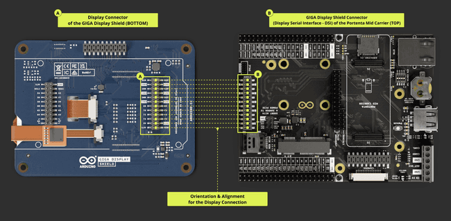
The following image shows the orientation of the connection between the GIGA Display Shield and the Portenta Mid Carrier.
For a more detailed connection orientation with a brief pinout designation, the following diagram might help you understand how to stack the GIGA Display Shield to the Portenta Mid Carrier.
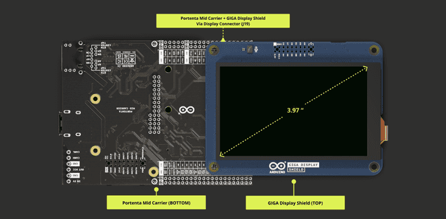
Once you have aligned and connected the Portenta Mid Carrier with the GIGA Display Shield, you should have a similar setup as in the following image:
Using Linux
To review the current device tree overlay configurations, which are crucial for hardware feature management and system customization, to interface with the GIGA Display Shield, use the following command:
1fw_printenv overlaysThis command invokes the
fw_printenvThis can include enabling additional peripherals, configuring pin mappings, or activating specific hardware features, providing a flexible approach to hardware customization. From this, the following overlay should be available:
1ov_carrier_mid_dsi_panelIf it is not present, the following steps will help you to set the needed overlays to use the GIGA Display Shield. Access the docker container named x8-devel with the following command:
1docker exec -it x8-devel shThis command uses docker exec to begin a new shell session inside the running x8-devel container. The
-itWe need to search for tenta_runner Python script, and the following command can help to locate the script:
1find / -name *.pyStarting from the root directory, this command recursively searches for files ending in
.pyHaving located the tenta_runner.py, navigate to the directory using the following command:
1cd /root/examples/tenta-configRun the tenta_runner.py script using the following command:
1python tenta_runner.pyThe script will bring up a GUI within the
tenta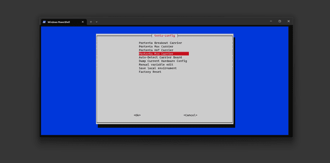
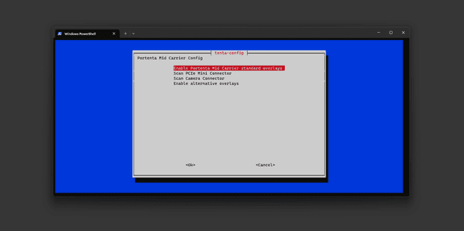
It will then show a list of available options that can be executed within the Portenta Mid Carrier platform. Here, the Enable alternative overlays option will be selected.
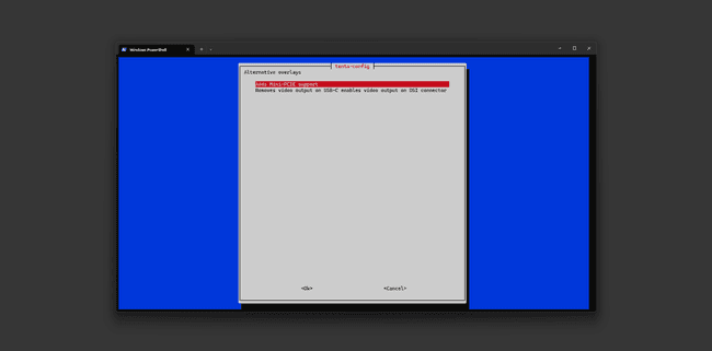
Because the GIGA Display Shield will be used, Removes video output on USB-C enables video output on DSI connector configuration will be selected. This configuration will disable video output via the USB-C connector and switch the video output to be available to the DSI connector.
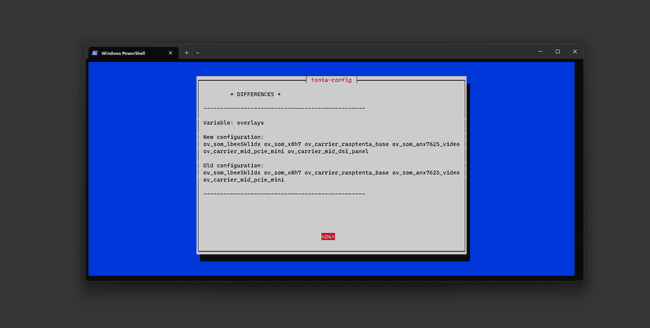
Once selected, it will prompt a message showing differences that overlays will have after the change.
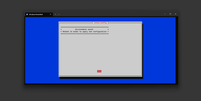
Proceed to accept with Ok, and the device will now be ready with the overlays to enable video output on the DSI connector.
We can now observe if the GIGA Display Shield is powered on and ready for use, having the shield connected to the Portenta Mid Carrier.
Using Arduino IDEs
With the Portenta H7, it is possible to use the following example:
1/*2 ArduinoLogo3
4 created 17 Apr 20235 by Leonardo Cavagnis6*/7
8#include "Arduino_H7_Video.h"9#include "ArduinoGraphics.h"10
11#include "img_arduinologo.h"12// Alternatively, any raw RGB565 image can be included on demand using this macro13// Online image converter: https://lvgl.io/tools/imageconverter (Output format: Binary RGB565)14/*15#define INCBIN_PREFIX16#include "incbin.h"17INCBIN(test, "/home/user/Downloads/test.bin");18*/19
20Arduino_H7_Video Display(800, 480, GigaDisplayShield);21//Arduino_H7_Video Display(1024, 768, USBCVideo);22
23Image img_arduinologo(ENCODING_RGB16, (uint8_t *) texture_raw, 300, 300);24
25void setup() {26 Display.begin();27
28 Display.beginDraw();29 Display.image(img_arduinologo, (Display.width() - img_arduinologo.width())/2, (Display.height() - img_arduinologo.height())/2);30 Display.endDraw();31}32
33void loop() { }It will require the ArduinoGraphics library installed to compile the code without any issues.
The example can be found within the Arduino IDE, and it is located under File -> Examples -> Portenta_H7_Video. The name of the example is ArduinoLogo.
Once the example has been compiled and uploaded to the Portenta H7, you will be able to see the Arduino logo drawn on the GIGA Display Shield.
CAN FD (Onboard Transceiver)
The Portenta Mid Carrier is equipped with a CAN bus port that connects to a screw terminal block. This bus incorporates the TJA1049 module. This high-speed CAN FD transceiver is integral to the Portenta Mid Carrier.
The TJA1049 module complies with various standards, including ISO 11898-2:2016, SAE J2284-1, and SAE J2284-5. These standards pertain to the CAN physical layer, ensuring reliable communication, especially during the fast phase of CAN FD.
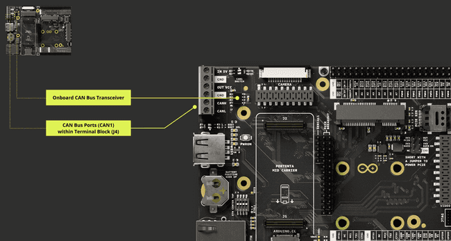
Since CAN FD is accessible within the screw terminal block, we have highlighted the CAN bus ports within the screw terminal block pinout for reference. It is important to know that the onboard transceiver is attached for CAN1. The CAN bus port is controlled via the DIP switch for CANH and CANL lines. The following table shows the Screw Terminal Block (J4) with CAN1 Bus that is connected to the onboard transceiver of the Portenta Mid Carrier:
| Pin Number | Silkscreen Pin | Power Net | Portenta Standard Pin | High-Density Pin |
|---|---|---|---|---|
| 1 | VIN | +5V (In/Out) | VIN | J1-21, J1-32, J1-41, J1-48 |
| 2 | GND | Ground | GND | J1-22, J1-31, J1-42, J1-47, J1-54, J2-24, J2-33, J2-44, J2-57, J2-70 |
| 3 | VCC | +3V3 Portenta (Out) | VCC | J2-23, J2-34, J2-43, J2-69 |
| 4 | GND | Ground | GND | J1-22, J1-31, J1-42, J1-47, J1-54, J2-24, J2-33, J2-44, J2-57, J2-70 |
| 5 | CANH | J1-49 (Through U2) | ||
| 6 | CANL | J1-51 (Through U2) |
For stable CAN bus communication, it is recommended to install a 120 Ω termination resistor between CANH and CANL lines.
For more information on implementing the CAN Bus protocol, you can go directly to the CAN Bus section in the Communication section.
CAN FD (External Transceiver)
In addition to the onboard TJA1049 transceiver, the Portenta Mid Carrier allows for the integration of external CAN FD transceivers. This flexibility is crucial for applications requiring multiple CAN networks or specific transceiver characteristics not provided by the onboard module.
Integrating an external CAN FD transceiver involves connecting it to the Portenta Mid Carrier's I/O ports. Ensuring the external transceiver is compatible with the CAN FD protocol and adheres to relevant standards such as ISO 11898-2:2016.
The connection typically involves linking the transceiver's CANH and CANL lines to the respective pins (CAN0 TX/RX) on the Mid Carrier. Power and ground connections must be established according to the transceiver's specifications.
Some technical considerations must be taken into account as well:
Compatibility: Ensure the external transceiver is compatible with the Portenta Mid Carrier's voltage levels and pin configurations.
Termination Resistors: Like the onboard transceiver, it is recommended to use a 120 Ω termination resistor between the CANH and CANL lines of the external transceiver to ensure signal integrity.
Software Configuration: Depending on the external transceiver used, software configuration might be necessary to establish communication between the Portenta Mid Carrier and the external module.
This could involve setting up the correct CAN baud rate, configuring the CAN controller, and defining message filters.
There are some advantages to using an external transceiver:
Customization: Users can select a transceiver with specific features such as higher fault tolerance, different voltage levels, or advanced diagnostics capabilities.
Enhanced Performance: Some external transceivers might offer better performance regarding data rates or reliability in specific environmental conditions.
Redundancy and Multiple Networks: External transceivers provide an effective solution for systems that require redundancy or need to connect to multiple CAN networks simultaneously.
Using an external CAN FD transceiver with the Portenta Mid Carrier makes it possible to customize the CAN network setup to specific requirements, ensuring both flexibility and robust application performance.
For detailed information about the CAN Bus protocol implementation, please refer to the CAN Bus section in the Communication section.
Storage Options
The Portenta Mid Carrier enhances its capabilities by offering storage options for data logging operations, allowing for effective data storage management. This sub-section provides insights into the onboard storage options and how to access and use them.
MicroSD Storage (J12)
The carrier features a microSD card slot, offering the option to expand storage capacity significantly. This is particularly useful for handling large volumes of data, such as sensor logs or onboard computer registries.
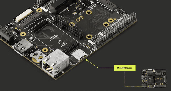
The detailed connector designation for the microSD slot is as follows:
| Pin number | Silkscreen | Power Net | Portenta HD Standard Pin | High-Density Pin |
|---|---|---|---|---|
| 1 | N/A | SDC_D2 | J1-63 | |
| 2 | N/A | SDC_D3 | J1-65 | |
| 3 | N/A | SDC_CMD | J1-57 | |
| 4 | N/A | VDD_SDCARD | VSD | J1-72 |
| 5 | N/A | SDC_CLK | J1-55 | |
| 6 | N/A | GND | GND | J1-22, J1-31, J1-42, J1-47, J1-54, J2-24, J2-33, J2-44, J2-57, J2-70 |
| 7 | N/A | SDC_D0 | J1-59 | |
| 8 | N/A | SDC_D1 | J1-61 | |
| CD1 | N/A | SDC_CD | J1-67 | |
| CD2 | N/A | GND | GND | J1-22, J1-31, J1-42, J1-47, J1-54, J2-24, J2-33, J2-44, J2-57, J2-70 |
Using Linux
To use a microSD card with the Portenta X8, run the following command to fetch a Docker container. This container eases the setup of elements essential for the microSD card interaction:
1docker run -it --cap-add SYS_ADMIN --device /dev/mmcblk1p1 debian:stable-slim bashThe command launches the image immediately after successfully downloading the container image. You will be directed inside the container once it is operational.
First, locate the partition scheme of the microSD card. If it lacks a partition table, create partitions using the
fdiskTo check if the Portenta X8 has detected the microSD card, enter either of these commands:
1lsblk2
3# or4fdisk -lThe microSD card typically appears as
/dev/mmcblk0/dev/sdXBefore accessing the microSD card's contents, mount it. Create a directory to use as a mount point:
1mkdir -p /tmp/sdcardMount the microSD card to the previously defined directory with the correct partition number (e.g.,
p11mount /dev/mmcblk1p1 /tmp/sdcardYou can navigate to the mount point and view the contents of the microSD card:
1cd /tmp/sdcard2lsThe' echo' command is useful for writing data on the microSD card. For instance, to make a hello.txt file with
"Hello World Carrier!"1echo "Hello World Carrier!" > hello.txtTo read the contents of the file you have just created:
1cat hello.txtThis displays the saved content in hello.txt on your present shell.
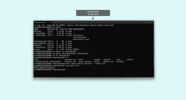
Once you are done with the operations related to the microSD card, proceed to unmount its partition properly:
1umount /tmp/sdcardIf you need to format the SD card to the ext4 filesystem, use the following command. Please be cautious, as this will remove all data on the microSD card.
1# Please be aware that this command will erase all data on the microSD card.2mkfs.ext4 /dev/mmcblk1p1With this, you could write and read a text file on a microSD card using the Portenta X8 and Mid Carrier.
Using Arduino IDE
To learn how the microSD card slot works for enhanced storage with the Arduino IDE, please follow this guide.
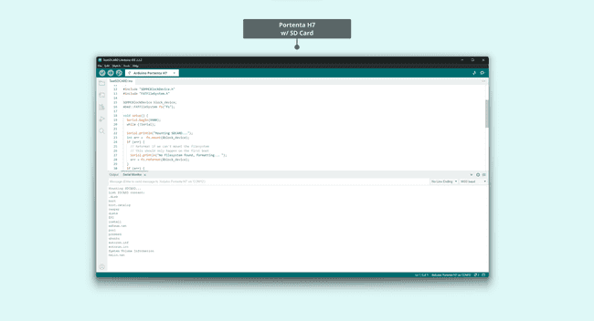
For Portenta H7, you can use the following Arduino IDE script to test the mounted SD card within the Portenta Mid Carrier:
1#include "SDMMCBlockDevice.h"2#include "FATFileSystem.h"3
4SDMMCBlockDevice block_device;5mbed::FATFileSystem fs("fs");6
7void setup() {8 Serial.begin(9600);9 while (!Serial);10
11 Serial.println("Mounting SDCARD...");12 int err = fs.mount(&block_device);13 if (err) {14 // Reformat if we can't mount the filesystem15 // this should only happen on the first boot16 Serial.println("No filesystem found, formatting... ");17 err = fs.reformat(&block_device);18 }19 if (err) {20 Serial.println("Error formatting SDCARD ");21 while(1);22 }23
24 DIR *dir;25 struct dirent *ent;26 int dirIndex = 0;27
28 Serial.println("List SDCARD content: ");29 if ((dir = opendir("/fs")) != NULL) {30 // Print all the files and directories within directory (not recursively)31 while ((ent = readdir (dir)) != NULL) {32 Serial.println(ent->d_name);33 dirIndex++;34 }35 closedir (dir);36 } else {37 // Could not open directory38 Serial.println("Error opening SDCARD\n");39 while(1);40 }41 if(dirIndex == 0) {42 Serial.println("Empty SDCARD");43 }44}45
46void loop() {47 // Empty48}If the micro SD card has been successfully detected and mounted, you will be able to see the list of the files printed on the Arduino IDE's Serial Monitor:
For Portenta C33, consider the following script for testing a mounted SD card.
1#include <vector>2#include <string>3#include "SDCardBlockDevice.h"4#include "FATFileSystem.h"5
6#define TEST_FS_NAME "fs"7#define TEST_FOLDER_NAME "TEST_FOLDER"8#define TEST_FILE "test.txt"9#define DELETE_FILE_DIMENSION 15010
11
12SDCardBlockDevice block_device(PIN_SDHI_CLK, PIN_SDHI_CMD, PIN_SDHI_D0, PIN_SDHI_D1, PIN_SDHI_D2, PIN_SDHI_D3, PIN_SDHI_CD, PIN_SDHI_WP);13FATFileSystem fs(TEST_FS_NAME);14
15std::string root_folder = std::string("/") + std::string(TEST_FS_NAME);16std::string folder_test_name = root_folder + std::string("/") + std::string(TEST_FOLDER_NAME);17std::string file_test_name = folder_test_name + std::string("/") + std::string(TEST_FILE);18
19void setup() {20 /*21 * SERIAL INITIALIZATION22 */23 Serial.begin(9600);24 while(!Serial) {25
26 }27
28 /* list to store all directory in the root */29 std::vector<std::string> dir_list;30
31 Serial.println();32 Serial.println("##### TEST SD CARD with FAT FS");33 Serial.println();34
35 /*36 * MOUNTING SDCARD AS FATFS filesystem37 */38 Serial.println("Mounting SDCARD...");39 int err = fs.mount(&block_device);40 if (err) {41 // Reformat if we can't mount the filesystem42 // this should only happen on the first boot43 Serial.println("No filesystem found, formatting... ");44 err = fs.reformat(&block_device);45 }46 if (err) {47 Serial.println("Error formatting SDCARD ");48 while(1);49 }50
51 /*52 * READING root folder53 */54
55 DIR *dir;56 struct dirent *ent;57 int dirIndex = 0;58
59 Serial.println("*** List SD CARD content: ");60 if ((dir = opendir(root_folder.c_str())) != NULL) {61 while ((ent = readdir (dir)) != NULL) {62
63 if(ent->d_type == DT_REG) {64 Serial.print("- [File]: ");65 }66
67 else if(ent->d_type == DT_DIR) {68 Serial.print("- [Fold]: ");69 dir_list.push_back(ent->d_name);70 }71 Serial.println(ent->d_name);72 dirIndex++;73 }74 closedir (dir);75 }76 else {77 // Could not open directory78 Serial.println("Error opening SDCARD\n");79 while(1);80 }81
82 if(dirIndex == 0) {83 Serial.println("Empty SDCARD");84 }85
86 bool found_test_folder = false;87
88 /*89 * LISTING CONTENT of the first level folders (the one immediately present in root folder)90 */91
92 if(dir_list.size()) {93 Serial.println();94 Serial.println("Listing content of folders in root: ");95 }96 for(unsigned int i = 0; i < dir_list.size(); i++) {97 if(dir_list[i] == TEST_FOLDER_NAME) {98 found_test_folder = true;99 }100 Serial.print("- ");101 Serial.print(dir_list[i].c_str());102 Serial.println(":");103
104 std::string d = root_folder + std::string("/") + dir_list[i];105 if ((dir = opendir(d.c_str())) != NULL) {106 while ((ent = readdir (dir)) != NULL) {107 if(ent->d_type == DT_REG) {108 Serial.print(" - [File]: ");109 }110 else if(ent->d_type == DT_DIR) {111 Serial.print(" - [Fold]: ");112 }113 Serial.println(ent->d_name);114 }115 closedir (dir);116 }117 else {118 Serial.print("ERROR OPENING SUB-FOLDER ");119 Serial.println(d.c_str());120 }121 }122
123 /*124 * CREATING TEST FOLDER (if does not exist already)125 */126
127 err = 0;128 if(!found_test_folder) {129 Serial.println("TEST FOLDER NOT FOUND... creating folder test");130 err = mkdir(folder_test_name.c_str(), S_IRWXU | S_IRWXG | S_IRWXO);131 if(err != 0) {132 Serial.print("FAILED folder creation with error ");133 Serial.println(err);134 }135 }136
137 /*138 * READING TEST FILE CONTENT139 */140
141 if(err == 0) {142 int file_dimension = 0;143 FILE* fp = fopen(file_test_name.c_str(), "r");144 if(fp != NULL) {145 Serial.print("Opened file: ");146 Serial.print(file_test_name.c_str());147 Serial.println(" for reading");148
149 fseek(fp, 0L, SEEK_END);150 int numbytes = ftell(fp);151 fseek(fp, 0L, SEEK_SET);152
153 Serial.print("Bytes in the file: ");154 Serial.println(numbytes);155 file_dimension = numbytes;156
157 if(numbytes > 0) {158 Serial.println();159 Serial.println("-------------------- START FILE CONTENT --------------------");160 }161
162 for(int i = 0; i < numbytes; i++) {163 char ch;164 fread(&ch, sizeof(char), 1, fp);165 Serial.print(ch);166 }167
168 if(numbytes > 0) {169 Serial.println("--------------------- END FILE CONTENT ---------------------");170 Serial.println();171 }172 else {173 Serial.println("File is EMPTY!");174 Serial.println();175 }176
177 fclose(fp);178 }179 else {180 Serial.print("FAILED open file ");181 Serial.println(file_test_name.c_str());182 }183
184 /*185 * DELETE FILE IF THE File dimension is greater than 150 bytes186 */187
188 if(file_dimension > DELETE_FILE_DIMENSION) {189 Serial.println("Test file reached the delete dimension... deleting it!");190 if(remove(file_test_name.c_str()) == 0) {191 Serial.println("TEST FILE HAS BEEN DELETED!");192 }193 }194
195 /*196 * APPENDING SOMETHING TO FILE197 */198
199 fp = fopen(file_test_name.c_str(), "a");200 if(fp != NULL) {201 Serial.print("Opened file: ");202 Serial.print(file_test_name.c_str());203 Serial.println(" for writing (append)");204 char text[] = "This line has been appended to file!\n";205 fwrite(text, sizeof(char), strlen(text), fp);206 fclose(fp);207 }208 else {209 Serial.print("FAILED open file for appending ");210 Serial.println(file_test_name.c_str());211 }212
213 /*214 * READING AGAIN FILE CONTENT215 */216
217 fp = fopen(file_test_name.c_str(), "r");218 if(fp != NULL) {219 Serial.print("Opened file: ");220 Serial.print(file_test_name.c_str());221 Serial.println(" for reading");222
223 fseek(fp, 0L, SEEK_END);224 int numbytes = ftell(fp);225 fseek(fp, 0L, SEEK_SET);226
227 Serial.print("Bytes in the file: ");228 Serial.println(numbytes);229
230 if(numbytes > 0) {231 Serial.println();232 Serial.println("-------------------- START FILE CONTENT --------------------");233 }234
235 for(int i = 0; i < numbytes; i++) {236 char ch;237 fread(&ch, sizeof(char), 1, fp);238 Serial.print(ch);239 }240
241 if(numbytes > 0) {242 Serial.println("--------------------- END FILE CONTENT ---------------------");243 Serial.println();244 }245 else {246 Serial.println("File is EMPTY!");247 Serial.println();248 }249
250 fclose(fp);251
252 }253 else {254 Serial.print("FAILED open file for appending ");255 Serial.println(file_test_name.c_str());256 }257 }258
259}260
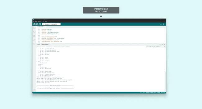
261void loop() {262 // Empty263}Once the micro SD card is recognized and accessed, its files will be shown in the Arduino IDE's Serial Monitor:
USB Interface (J13)
The Portenta Mid Carrier is equipped with a USB interface, which is USB 2.0, designed for data logging purposes.
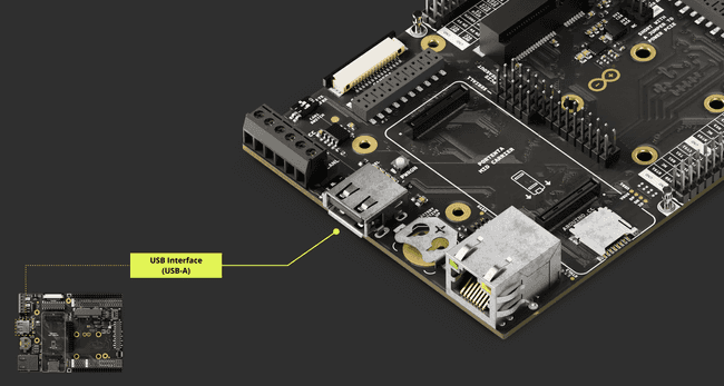
For those interested in the specifics of the USB-A port's pinout, the table below provides detailed information on how the connections are distributed:
| Pin Number | Silkscreen Pin | Power Net | Portenta Standard Pin | High-Density Pin |
|---|---|---|---|---|
| 1 | N/A | +5V (In/Out) | VIN | J1-21, J1-32, J1-41, J1-48 |
| 2 | N/A | USB0_D_N | J1-28 | |
| 3 | N/A | USB0_D_P | J1-26 | |
| 4 | N/A | Ground | GND | J1-22, J1-31, J1-42, J1-47, J1-54, J2-24, J2-33, J2-44, J2-57, J2-70 |
This USB-A interface can accommodate devices such as storage drives for data logging.
Using Linux
To demonstrate a write operation on a USB memory drive using the Portenta X8's shell, follow this sequence of commands:
1sudo su -First, switch to root mode to obtain necessary permissions for mounting and unmounting peripherals, such as a USB memory drive.
1lsblkThe
lsblk/dev/sda1A helpful tip to pinpoint the newly connected USB drive is to run
lsblklsusb1mkdir -p /mnt/USBmountHere,
mkdir -p/mnt/USBmount1mount -t vfat /dev/sda1 /mnt/USBmountThis command mounts the USB drive (presumed to have a FAT filesystem, vfat) at
/dev/sda1/mnt/USBmount/mnt/USBmount1cd /mnt/USBmountAn
ls1lsTo create a simple text file with the message
Hello, World!1dd if=<(echo -n "Hello, World!") of=/mnt/USBmount/helloworld.txtThis command uses
ddechoHello, World!dd/mnt/USBmountTo read and display the file's contents in the shell:
1cat helloworld.txtThe
catHello, World!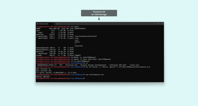
With these steps, you can effectively manage external storage devices like USB sticks or hard drives, expanding the storage capabilities of your solution with the Portenta Mid Carrier.
Using Arduino IDE
The following example illustrates the process of using the USB interface on the Portenta Mid Carrier with the Portenta C33 to interface with a Mass Storage Device (MSD).
By implementing this example, you can connect with and access data on a USB storage device, thus simplifying managing external storage through the USB interface.
1#include <vector>2#include <string>3#include "UsbHostMsd.h"4#include "FATFileSystem.h"5
6#define TEST_FS_NAME "usb"7#define TEST_FOLDER_NAME "TEST_FOLDER"8#define TEST_FILE "test.txt"9#define DELETE_FILE_DIMENSION 15010
11
12USBHostMSD block_device;13FATFileSystem fs(TEST_FS_NAME);14
15std::string root_folder = std::string("/") + std::string(TEST_FS_NAME);16std::string folder_test_name = root_folder + std::string("/") + std::string(TEST_FOLDER_NAME);17std::string file_test_name = folder_test_name + std::string("/") + std::string(TEST_FILE);18
19/* this callback will be called when a Mass Storage Device is plugged in */20void device_attached_callback(void) {21 Serial.println();22 Serial.println("++++ Mass Storage Device detected ++++");23 Serial.println();24}25
26void setup() {27 /*28 * SERIAL INITIALIZATION29 */30 Serial.begin(9600);31 while(!Serial) {32
33 }34
35 Serial.println();36 Serial.println("*** USB HOST Mass Storage Device example ***");37 Serial.println();38
39 /* attached the callback so that when the device is inserted the device_attached_callback40 will be automatically called */41 block_device.attach_detected_callback(device_attached_callback);42 /* list to store all directory in the root */43 std::vector<std::string> dir_list;44
45 /*46 * Check for device to be connected47 */48
49 int count = 0;50 while (!block_device.connect()) {51 if(count == 0) {52 Serial.println("Waiting for Mass Storage Device");53 }54 else {55 Serial.print(".");56 if(count % 30 == 0) {57 Serial.println();58 }59 }60 count++;61 delay(1000);62 }63
64 Serial.println("Mass Storage Device connected.");65
66 /*67 * MOUNTING SDCARD AS FATFS filesystem68 */69
70 Serial.println("Mounting Mass Storage Device...");71 int err = fs.mount(&block_device);72 if (err) {73 // Reformat if we can't mount the filesystem74 // this should only happen on the first boot75 Serial.println("No filesystem found, formatting... ");76 err = fs.reformat(&block_device);77 }78
79 if (err) {80 Serial.println("Error formatting USB Mass Storage Device");81 while(1);82 }83
84 /*85 * READING root folder86 */87
88 DIR *dir;89 struct dirent *ent;90 int dirIndex = 0;91
92 Serial.println("*** List USB Mass Storage Device content: ");93 if ((dir = opendir(root_folder.c_str())) != NULL) {94 while ((ent = readdir (dir)) != NULL) {95 if(ent->d_type == DT_REG) {96 Serial.print("- [File]: ");97 }98 else if(ent->d_type == DT_DIR) {99 Serial.print("- [Fold]: ");100 if(ent->d_name[0] != '.') { /* avoid hidden folders (.Trash might contain a lot of files) */101 dir_list.push_back(ent->d_name);102 }103 }104 Serial.println(ent->d_name);105 dirIndex++;106 }107 closedir (dir);108 }109 else {110 // Could not open directory111 Serial.println("Error opening USB Mass Storage Device\n");112 while(1);113 }114
115 if(dirIndex == 0) {116 Serial.println("Empty SDCARD");117 }118
119 bool found_test_folder = false;120
121 /*122 * LISTING CONTENT of the first level folders (the one immediately present in root folder)123 */124
125 if(dir_list.size()) {126 Serial.println();127 Serial.println("Listing content of folders in root: ");128 }129 for(unsigned int i = 0; i < dir_list.size(); i++) {130 if(dir_list[i] == TEST_FOLDER_NAME) {131 found_test_folder = true;132 }133 Serial.print("- ");134 Serial.print(dir_list[i].c_str());135 Serial.println(":");136
137 std::string d = root_folder + std::string("/") + dir_list[i];138 if ((dir = opendir(d.c_str())) != NULL) {139 while ((ent = readdir (dir)) != NULL) {140 if(ent->d_type == DT_REG) {141 Serial.print(" - [File]: ");142 }143 else if(ent->d_type == DT_DIR) {144 Serial.print(" - [Fold]: ");145 }146 Serial.println(ent->d_name);147 }148 closedir (dir);149 }150 else {151 Serial.print("ERROR OPENING SUB-FOLDER ");152 Serial.println(d.c_str());153 }154 }155
156 /*157 * CREATING TEST FOLDER (if does not exist already)158 */159
160 err = 0;161 if(!found_test_folder) {162 Serial.println("TEST FOLDER NOT FOUND... creating folder test");163 err = mkdir(folder_test_name.c_str(), S_IRWXU | S_IRWXG | S_IRWXO);164 if(err != 0) {165 Serial.print("FAILED folder creation with error ");166 Serial.println(err);167 }168 }169
170 /*171 * READING TEST FILE CONTENT172 */173
174 if(err == 0) {175 int file_dimension = 0;176 FILE* fp = fopen(file_test_name.c_str(), "r");177 if(fp != NULL) {178 Serial.print("Opened file: ");179 Serial.print(file_test_name.c_str());180 Serial.println(" for reading");181
182 fseek(fp, 0L, SEEK_END);183 int numbytes = ftell(fp);184 fseek(fp, 0L, SEEK_SET);185
186 Serial.print("Bytes in the file: ");187 Serial.println(numbytes);188 file_dimension = numbytes;189
190 if(numbytes > 0) {191 Serial.println();192 Serial.println("-------------------- START FILE CONTENT --------------------");193 }194
195 for(int i = 0; i < numbytes; i++) {196 char ch;197 fread(&ch, sizeof(char), 1, fp);198 Serial.print(ch);199 }200
201 if(numbytes > 0) {202 Serial.println("--------------------- END FILE CONTENT ---------------------");203 Serial.println();204 }205 else {206 Serial.println("File is EMPTY!");207 Serial.println();208 }209
210 fclose(fp);211 }212 else {213 Serial.print("FAILED open file ");214 Serial.println(file_test_name.c_str());215 }216
217 /*218 * DELETE FILE IF THE File dimension is greater than 150 bytes219 */220
221 if(file_dimension > DELETE_FILE_DIMENSION) {222 Serial.println("Test file reached the delete dimension... deleting it!");223 if(remove(file_test_name.c_str()) == 0) {224 Serial.println("TEST FILE HAS BEEN DELETED!");225 }226 }227
228 /*229 * APPENDING SOMETHING TO FILE230 */231
232 fp = fopen(file_test_name.c_str(), "a");233 if(fp != NULL) {234 Serial.print("Opened file: ");235 Serial.print(file_test_name.c_str());236 Serial.println(" for writing (append)");237 char text[] = "This line has been appended to file!\n";238 fwrite(text, sizeof(char), strlen(text), fp);239 fclose(fp);240 }241 else {242 Serial.print("FAILED open file for appending ");243 Serial.println(file_test_name.c_str());244 }245
246 /*247 * READING AGAIN FILE CONTENT248 */249
250 fp = fopen(file_test_name.c_str(), "r");251 if(fp != NULL) {252 Serial.print("Opened file: ");253 Serial.print(file_test_name.c_str());254 Serial.println(" for reading");255
256 fseek(fp, 0L, SEEK_END);257 int numbytes = ftell(fp);258 fseek(fp, 0L, SEEK_SET);259
260 Serial.print("Bytes in the file: ");261 Serial.println(numbytes);262
263 if(numbytes > 0) {264 Serial.println();265 Serial.println("-------------------- START FILE CONTENT --------------------");266 }267
268 for(int i = 0; i < numbytes; i++) {269 char ch;270 fread(&ch, sizeof(char), 1, fp);271 Serial.print(ch);272 }273
274 if(numbytes > 0) {275 Serial.println("--------------------- END FILE CONTENT ---------------------");276 Serial.println();277 }278 else {279 Serial.println("File is EMPTY!");280 Serial.println();281 }282
283 fclose(fp);284
285 }286 else {287 Serial.print("FAILED open file for appending ");288 Serial.println(file_test_name.c_str());289 }290 }291
292}293
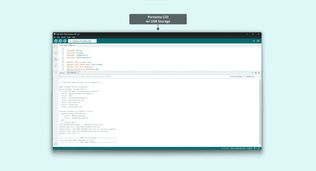
294void loop() {295 // Empty296}The image below shows a list of the files contained within the mounted USB storage device:
Configuration and Control
Configuration and control features allow users to customize the device's behavior for specific needs. If you want to learn how to set up network connectivity or adjust switch configurations, follow the section below.
DIP Switch Configuration
The Portenta Mid Carrier features DIP switches, enabling users to customize the board's behavior. These switches are designated for specific functions:
- Flashing mode
- Ethernet behavior
- CAN FD (CAN1)
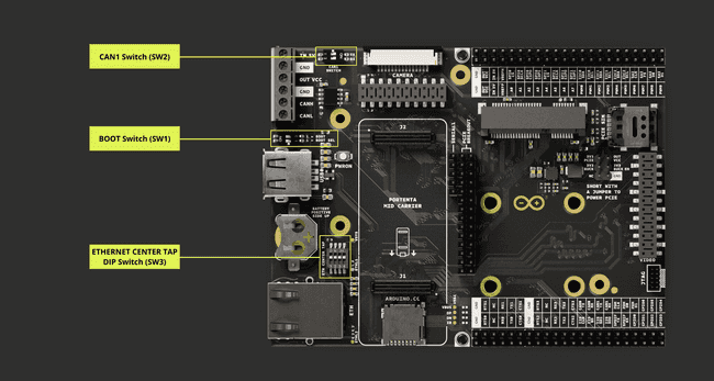
BOOT DIP Switch
For setting Flashing mode, the BOOT DIP switch is used. Adjustments to this switch enable the following behaviors:
| DIP Switch Designation | Position: ON | Position: OFF |
|---|---|---|
| BOOT | Flashing Mode | Normal Mode |
| BOOT SEL | Flashing Mode | Normal Mode |
Setting the BOOT SEL and BOOT DIP switch to the
ONuuuFor more information on how to flash an OS image of the Portenta X8, please check this tutorial.
ETH CENTER TAP DIP Switch
The configuration for Ethernet is managed using the ETH CENTER TAP DIP switch. Such switch adjustments provide the following behaviors:
| DIP Switch Designation | Position: ON | Position: OFF |
|---|---|---|
| 1 | Ethernet Disabled | Ethernet Enabled |
| 2 | Ethernet Disabled | Ethernet Enabled |
| 3 | - | Ethernet Enabled |
| 4 | - | Ethernet Enabled |
This configuration applies to the Portenta X8. The Portenta H7 and C33, on the other hand, remain unaffected regardless of the switch positions.
Ethernet connection speeds differ based on the associated Portenta board:
- Portenta X8: 1 Gbit Ethernet
- Portenta H7 or C33: 10/100 Mbit Ethernet
CAN1 DIP Switch Configuration
The CAN FD (CAN1) configuration relies on the CAN1 SWITCH. Adjustments to this switch control the following behaviors:
| DIP Switch Designation | Position: ON | Position: OFF |
|---|---|---|
| TX | Onboard CAN Transceiver Active (CAN1) | Onboard CAN Transceiver Inactive (CAN1) |
| RX | Onboard CAN Transceiver Active (CAN1) | Onboard CAN Transceiver Inactive (CAN1) |
For optimal performance, it is recommended to use a 120 Ω termination resistor between the CANH and CANL lines.
Network Connectivity
The Portenta Mid Carrier enhances the networking capabilities of the Portenta family devices with its integrated Ethernet port and Cat.4 Module compatibility support via a Mini PCIe interface. This addition complements the existing Wi-Fi® and Bluetooth® features of the Portenta devices designed for use with this carrier.
This integration fully leverages wired and wireless communication methods in project developments. The Portenta devices' built-in wireless capabilities and adaptable protocol options, including the Mini PCIe interface for Cat.4 Module compatibility, create a comprehensive suite of communication solutions.
These features make the carrier ideal for a broad spectrum of applications with long-range coverage.
Cat.4 Modem (Cellular Connectivity)
The Cat.4 modem, designed for mPCIe interfaces, uses LTE (Long Term Evolution) standards. These modems are crucial for achieving high-speed data transmission in various electronic devices.
Cat.4 modems can deliver robust data speeds, with peak download rates of up to 150 Mbps and upload rates reaching 50 Mbps. This performance level is well-suited to various online activities, including high-definition video streaming and expedient large file transfers.
The mPCIe form factor of these modems ensures compatibility with compact devices, including laptops, tablets, and IoT (Internet of Things) systems. Furthermore, these modems maintain backward compatibility with 3G and 2G networks, offering comprehensive network connectivity in diverse locations.
The Portenta Mid Carrier takes advantage of this modem via an onboard mini PCIe interface and provides reliable 4G connectivity with backward compatibility for 3G and 2G networks. The Arduino Pro 4G Module (EMEA / GNSS Global), a Cat.4 modem mini PCIe card using PCI Express Mini Card 1.2 Standard Interface, will be the main protagonist of this section.
The following image represents the Arduino Pro 4G Module:
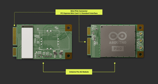
It is available in two variants, EMEA and Global (covering the US). This module can be integrated with various Portenta boards to create expansive smart cities/buildings and implement remote maintenance and fleet management systems.
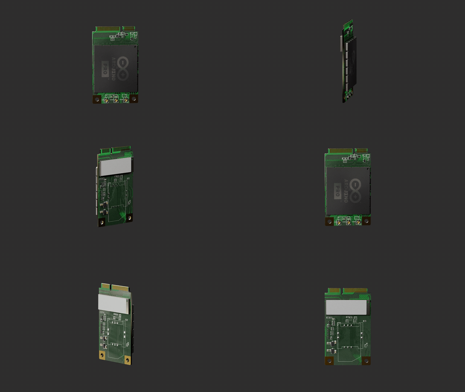
Make sure to attach external antennas to the Pro 4G Module to work correctly with wireless signals. There are three external antenna connectors: a main antenna connector, an Rx-diversity antenna connector, and a GNSS antenna connector. The impedance of the antenna connectors is 50 Ω.
Setting Up Via Out-Of-The-Box Experience
You can easily set up the modem through the Out-Of-The-Box process using the Portenta X8 and the Portenta Mid Carrier.
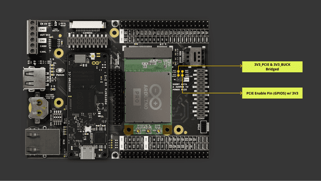
Please ensure the mini PCIe power configuration is set as outlined in the Mini PCIe Power Breakout Header section. The Portenta X8 needs the PCIE Enable (GPIO5) pin to be connected to a VCC (3V3) pin.
Please use a 5.0 V external power source when using an Arduino Pro 4G Module (EMEA / GNSS Global) or any other mPCIe modules due to their high power consumption. This is important for maintaining a stable power supply to the Portenta SOM and the carrier, particularly for extended periods of use.
Below is an image illustrating the expected setup, showing the Portenta X8 and Pro 4G Module combined with the Portenta Mid Carrier and mini PCIe power configuration:
If you are not familiar with the Out-Of-The-Box experience of the Portenta X8, it is recommended to read the Out-Of-The-Box Experience section of the Portenta X8 User Manual to gain a better understanding before proceeding.
Navigate to the Out-Of-The-Box dashboard of the Portenta X8.
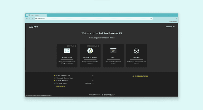
In this dashboard, you will find the Settings option. Please click on this option to proceed to the next step.
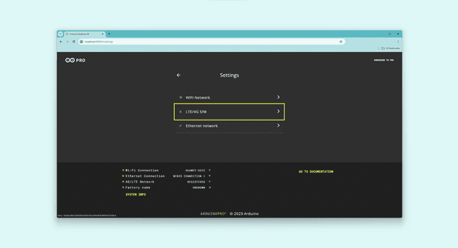
You will see three setup options in the Settings section. Select the LTE/4G Sim option to begin the modem setup.
Make sure the Pro 4G Module is connected to the mini PCIe slot at this stage, with the 3V3_PCIE pin of the Mini PCIe power breakout connected to the 3V3_BUCK of the same breakout header.
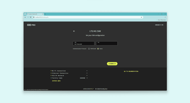
In the LTE/4G Sim setting, it will require you to provide the following:
- APN
- PIN (if available)
Additionally, it is necessary to select an Authentication Protocol, which could be either:
- PAP/CHAP
- NONE
Briefly, PAP (Password Authentication Protocol) sends credentials in plain text, suitable for low-security or legacy environments. At the same time, CHAP (Challenge-Handshake Authentication Protocol) improves security with three-way handshake and hash functions, protecting against replay attacks and providing a more secure option than PAP.
Make sure to provide these details according to your SIM card settings. After completing these steps, the bottom left of the Out-Of-The-Box interface will display the 4G/LTE Network connection status.
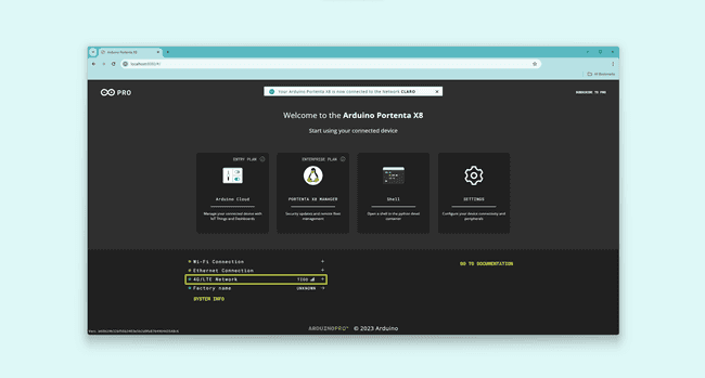
A notification will also appear briefly to inform you that the Portenta X8 has successfully established a network connection if it finds an available network. By selecting SYSTEM INFO, you can view detailed information about the established network connection.
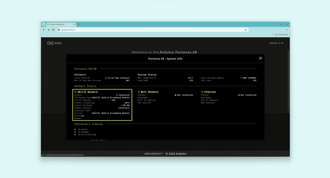
With this, you now have the Portenta X8 connected to a 4G/LTE network using the Portenta Mid Carrier through the Pro 4G Module.
Using Linux
The Pro 4G Module can be managed via ADB shell on the Portenta X8's Linux environment.
Make sure the mini PCIe power configuration is configured as described in the Mini PCIe Power Breakout Header section. The Portenta X8 requires the PCIE Enable (GPIO5) pin to be connected to a VCC (3V3) pin.
Please use a 5.0 V external power source when using an Arduino Pro 4G Module (EMEA / GNSS Global) or any other mPCIe modules due to their high power consumption. This is important for maintaining a stable power supply to the Portenta SOM and the carrier, particularly for extended periods of use.
The image below shows the anticipated configuration, featuring the Portenta X8 and Pro 4G Module integrated with the Portenta Mid Carrier, including the mini PCIe power configuration:

Once the setup is ready, the following sequence of commands is used to set the overlays required for the Portenta X8 and the Portenta Mid Carrier:
1fw_setenv carrier_custom 11fw_setenv is_on_carrier yes1fw_setenv carrier_name mid1fw_setenv overlays 'ov_som_lbee5kl1dx ov_som_x8h7 ov_carrier_breakout_usbfs ov_carrier_mid_pcie_mini'Alternatively, it is possible to use the tenta-config process implemented in the GIGA Display Connector's Linux Setup section to apply the overlays to enable mini PCIe for the Portenta Mid Carrier with the Portenta X8.
Please check out the guidelines in the GIGA Display Connector's Linux Setup section for detailed information on how the tenta-config works if you have yet to become familiar with the usage.
Access the docker container named x8-devel with the following command:
1docker exec -it x8-devel shNavigate to the directory using the following command:
1cd /root/examples/tenta-configRun the tenta_runner.py script using the following command:
1python tenta_runner.pyThe script will activate a user interface within the
tentaIt will open a new window displaying the Adds Mini-PCIE support option. Please select the Adds Mini-PCIE support option.
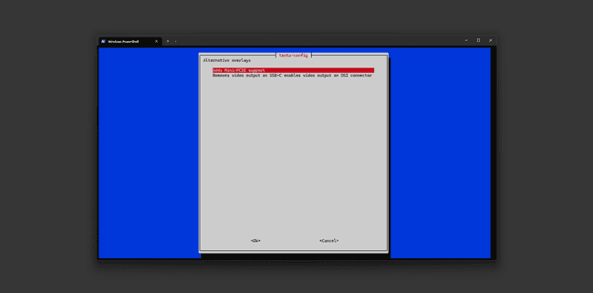
It will prompt a message showing a new set of overlays that will be applied once modified.
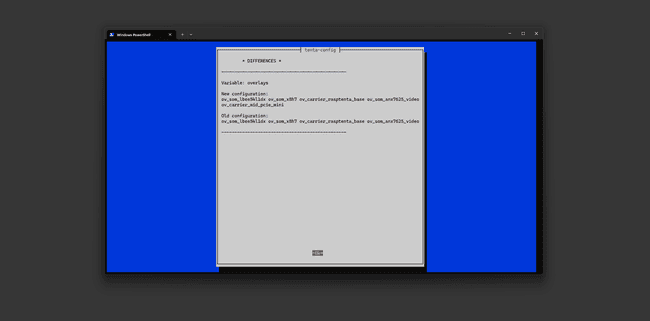
Select Ok to confirm, and the device will be configured with the overlays for mini PCIe support.
The module must be enabled, and this can be accomplished either by putting the GPIO 5 (iMX8 Pin 165) manually via the 3.3V line or by command as follows:
1echo 165 > /sys/class/gpio/export1echo out > /sys/class/gpio/gpio165/direction1echo 1 > /sys/class/gpio/gpio165/valueAfterward, the setup process involves bringing down the
wwan01ip link set dev wwan0 down1echo Y > /sys/class/net/wwan0/qmi/raw_ip1ip link set dev wwan0 upThe following steps include using
qmicli1qmicli --device=/dev/cdc-wdm0 --device-open-proxy --uim-get-card-status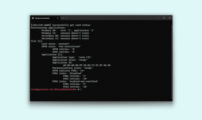
1qmicli --device=/dev/cdc-wdm0 --device-open-proxy --wds-start-network="ip-type=4,apn=iot.1nce.net" --client-no-release-cid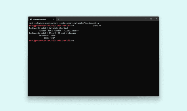
After establishing the network connection, you can use
udhcpc1udhcpc -q -f -n -i wwan0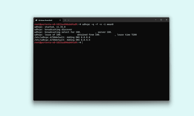
A speed test can be performed to test the speed and performance of the connection. It involves downloading the
speedtest-cli1wget -O speedtest-cli https://raw.githubusercontent.com/sivel/speedtest-cli/master/speedtest.py1chmod +x speedtest-cli1docker run python:3.8-slim-buster1docker run -it --mount type=bind,source="$(pwd)",target=/app python:3.8-slim-buster /bin/bash1/app/speedtest-cliOnce the speed test concludes, you can see similar behavior to the following image.

The download and upload speed may vary depending on the region.
This comprehensive setup shows how Mini PCIe cards can be integrated and used in compact systems as carriers, leveraging their ability to provide additional functionalities while maintaining a small footprint.
To compress into a single line of command, the following format is also suggested:
1nmcli c add type gsm ifname cdc-wdm0 con-name wwan0 apn hologram connection.autoconnect yesIn case the SIM card requires a PIN number, the format is modified slightly as follows:
1nmcli c add type gsm ifname cdc-wdm0 con-name wwan0 apn mobile.vodafone.it gsm.pin <PIN>Using Arduino IDE
The Portenta H7 and C33 are compatible with the Mini PCIe interface and can leverage the Pro 4G Module's capability. Enable and using the modem with the Portenta H7 or C33 will require a library named Arduino_4GModem.
The Arduino_4GModem library packs two sources:
- Arduino_4G_Module
- ArduinoProModem
Each source is included for the correct compilation and operation of the modem with either Portenta H7 or C33. The library manager within the Arduino IDE can access the library by navigating to Sketch -> Include Library -> Manage Libraries.
The library provides functionality for setting up a 4G connection, handling GPS/A-GPS location services, and uninterrupted SMS transactions.
Please ensure the mini PCIe power configuration is set as outlined in the Mini PCIe Power Breakout Header section. The Portenta H7 or C33 requires SERIAL1 Breakout pins to be connected to designated PCIe Breakout pins :
| SERIAL1 Breakout Pins (17) | PCIe Breakout Pins (16) |
|---|---|
| SERIAL1 RX | mPCIe_CK_P |
| SERIAL1 TX | mPCIe_CK_N |
| SERIAL1 RTS | mPCIe_RX_N |
| SERIAL1 CTS | mPCIe_RX_P |
| mPCIE_GPIO_RST (GPIO6) | mPCIe_RST |
Please use a 5.0 V external power source when using an Arduino Pro 4G Module (EMEA / GNSS Global) or any other mPCIe modules due to their high power consumption. This is important for maintaining a stable power supply to the Portenta SOM and the carrier, particularly for extended periods of use.
The image below shows the setup, featuring the Portenta H7 and Pro 4G Module connected to the Portenta Mid Carrier along with a mini PCIe power configuration:
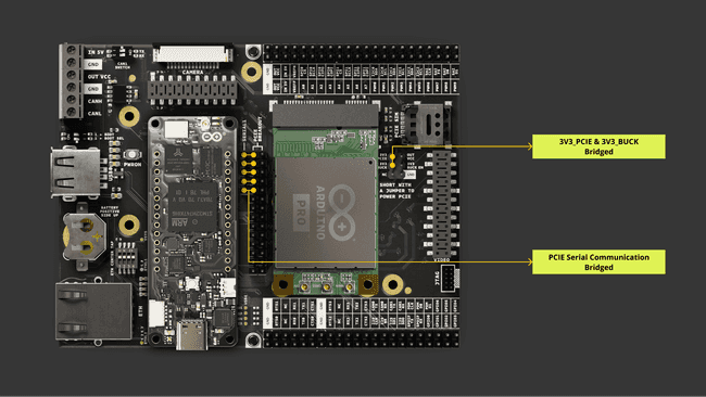
The Portenta H7 can be replaced with the Portenta C33, maintaining the same setup.
Once the setup is ready, we can use the following example from the library called HTTPClient:
1#define TINY_GSM_DEBUG2#define LOGGING3#define DEBUGSERIAL Serial4
5#include "ArduinoProModem.h"6
7const char apn[] = "APN";8const char gprsUser[] = "GPRSUSER";9const char gprsPass[] = "GPRSPASS";10
11const char server[] = "vsh.pp.ua";12const char resource[] = "/TinyGSM/logo.txt";13const int port = 80;14
15ArduinoCellularModem fourgee = ArduinoCellularModem();16HttpClient http = fourgee.getHTTPClient(server, port);17
18//HttpClient http = HttpClient(&fourgee.getNetworkClient(), server, port);19
20void setup(){21 Serial.begin(115200);22 while (!Serial);23 fourgee.begin();24 fourgee.connect(apn, gprsUser, gprsPass);25}26
27void loop(){28
29 Serial.print(F("Performing HTTP GET request... "));30 int err = http.get(resource);31 if (err != 0) {32 Serial.println(F("failed to connect"));33 delay(10000);34 return;35 }36
37 int status = http.responseStatusCode();38 Serial.print(F("Response status code: "));39 Serial.println(status);40 if (!status) {41 delay(10000);42 return;43 }44
45 Serial.println(F("Response Headers:"));46 while (http.headerAvailable()) {47 String headerName = http.readHeaderName();48 String headerValue = http.readHeaderValue();49 Serial.println(" " + headerName + " : " + headerValue);50 }51
52 int length = http.contentLength();53 if (length >= 0) {54 Serial.print(F("Content length is: "));55 Serial.println(length);56 }57 if (http.isResponseChunked()) {58 Serial.println(F("The response is chunked"));59 }60
61 String body = http.responseBody();62 Serial.println(F("Response:"));63 Serial.println(body);64
65 Serial.print(F("Body length is: "));66 Serial.println(body.length());67
68 // Shutdown69
70 http.stop();71 Serial.println(F("Server disconnected"));72
73}The example above connects to the web and fetches resources via HTTP. The script will require defining the following parameter fields:
- APN
- GPRS User
- GPRS Password
These three parameters will always be required to be defined to use the SIM functionalities within the modem. The image below shows an anticipated initial result of the modem detected and connecting to a 4G network:
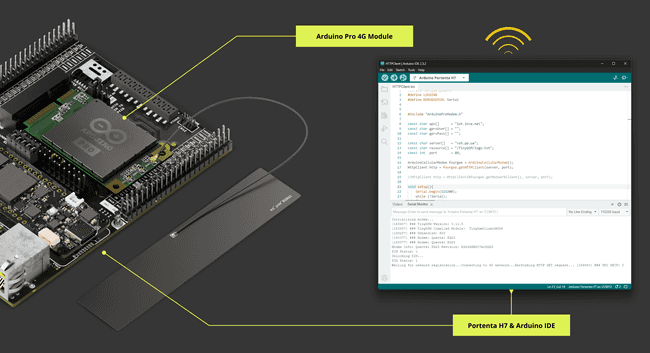
You may find additional examples as well within the library, each dedicated to different purposes as follows:
- MQTTClient: Stream sensor information via MQTT
- SMSReceive: Send and receive SMS messages
- TimeAndLocation: Get time and location using GPS and GSM as a fallback process for the EU version
Ethernet
The Portenta Mid Carrier features an Ethernet port with an RJ45 connector model TRJK7003A97NL with integrated magnetics. These magnetics are crucial for voltage isolation, noise suppression, signal quality maintenance, and rejecting common mode noise, ensuring adherence to waveform standards.
The connector supports the 1000MBASE-T standard, complying with IEEE 802.3ab, guaranteeing high-speed, reliable network connections for data-intensive industrial applications.
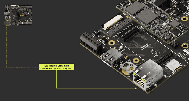
The following table shows an in-depth connector (J18) designation:
| Pin Number | Silkscreen Pin | Power Net | Portenta Standard Pin | High-Density Pin |
|---|---|---|---|---|
| 2 | ETH_C_N | J1-11 | ||
| 3 | N/A | ETH_C_P | J1-9 | |
| 4 | N/A | ETH_B_P | J1-5 | |
| 5 | N/A | ETH_B_N | J1-7 | |
| 8 | N/A | ETH_D_P | J1-13 | |
| 9 | N/A | ETH_D_N | J1-15 | |
| 10 | N/A | ETH_A_N | J1-3 | |
| 11 | N/A | ETH_A_P | J1-1 | |
| 13 | N/A | Ground | GND | J1-22, J1-31, J1-42, J1-47, J1-54, J2-24, J2-33, J2-44, J2-57, J2-70 |
| 14 | N/A | ETH_LED2 | J1-19 | |
| 15 | N/A | ETH_LED1 | J1-17 | |
| 16 | N/A | VCC | ||
| 17 | NC | NC | NC |
Ethernet connection speeds differ based on the associated Portenta board:
- With the Portenta X8: The system supports 1 Gbit Ethernet.
- When combined with the Portenta H7 or C33: The performance is limited to 100 Mbit Ethernet.
To configure the Ethernet settings, depending on the paired Portenta board, one must use the provided DIP switch on the Portenta Mid Carrier. The following table shows the specific DIP switch configuration needed to enable Ethernet on the carrier:
| DIP Switch Designation | Position: ON | Position: OFF |
|---|---|---|
| 1 | Ethernet Disabled | Ethernet Enabled |
| 2 | Ethernet Disabled | Ethernet Enabled |
| 3 | - | Ethernet Enabled |
| 4 | - | Ethernet Enabled |
For an in-depth understanding of the DIP switch, kindly refer to this section.
Connecting the Portenta X8 via the Portenta Mid Carrier to a DHCP-enabled device like a network router is recommended. This setup automatically assigns an IP address to the Portenta X8, simplifying communication with other network devices without needing manual IP configuration. Using DHCP eases device management, supports dynamic reconfiguration, and benefits applications involving numerous devices.
Suppose you manually assign an IP to your device or establish a direct network between your computer and the board. Depending on your network devices and operating system, various methods are available.
Using Linux
Using the Portenta X8 in combination with the Mid Carrier allows you to evaluate the Ethernet speed between your device and your computer in your network. First, ensure that the Portenta X8 is mounted on the Mid Carrier, and then connect them using an RJ45 LAN cable to your local network.
Ensure that your computer and your devices are connected to the same network, on the same IP range, and can see each other.
Subsequently, open a terminal to access the shell of the Portenta X8 with admin (root) privileges.
1adb shell2sudo su -When prompted, enter the password
fioTo use the iperf3 tool, we will set the Portenta X8 and Mid Carrier as the Server and the controlling computer as the Client. The commands will measure the bandwidth between the Portenta Mid Carrier with Portenta X8 and the computer. For a deeper understanding of iperf3, refer to its official documentation.
Begin by setting up the Portenta Mid Carrier with Portenta X8 as the Server. For the configuration of the necessary files to establish iperf3 on the device, follow the steps for Linux and Cygwin under General Build Instructions available here. In this case, we need the aarch64 / arm64 version. Thus, we need to execute the following commands:
1mkdir -p ~/bin && source ~/.profile1wget -qO ~/bin/iperf3 https://github.com/userdocs/iperf3-static/releases/latest/download/iperf3-arm64v81chmod 700 ~/bin/iperf3Once installed, iperf3 will be ready on your device. To ensure it operates without issues, run:
1chmod +x iperf3By following the provided instructions, the tool should be located in the Linux shell at:
1# ~bin/Check the tool's version using the following command within the
bin1./iperf3 -v
It should display the version information for the iperf3 tool.
Activate the Portenta Mid Carrier with Portenta X8 as a Server using the command:
1./iperf3 -sThis will set the Server to wait for connections via its IP address. It listens on port
5201-p1./iperf3 -s -p <Port Number>To identify the IP address of the Portenta X8, you can use either of the following commands and search for
eth01ifconfig2
3# Or4ip addr showNext, set up your computer as a Client. In this shared repository, select and download a version suitable for your system, like Windows x64.
Once you extract the content, you will notice the iperf3 file structure as follows:
1iperf32 |___bin3 |___include4 |___lib5 |___shareNavigate to bin and launch a terminal to prepare to use the tool. You can now begin a simple speed test using the following command.
1# For Linux shell2iperf3 -c <Server IP>3
4# For Windows5.\iperf3.exe -c <Server IP>This will set the computer as a Client and connect to the configured IP address. If a specific Port needs to be assigned, the following command will allow you to make such a configuration:
1.\iperf3.exe -c <Server IP> -p <Port Number>Upon starting the test, you will see the amount of data transferred and the corresponding bandwidth rate. With this, you can verify the Ethernet connection and its performance.
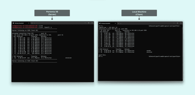
Going forward, we can use the following examples to test Ethernet connectivity.
If you desire to use Portenta X8 paired with Portenta Mid Carrier, please consider following Python® scripts. These scripts use the
library to create the socket and establish a computer network.socket
The below script would be used for Server side (TCP/IP) operations:
1#!/usr/bin/env python32
3import socket4
5def start_server():6 HOST = '127.0.0.1' # Localhost7 PORT = 65432 # Port to listen on8
9 with socket.socket(socket.AF_INET, socket.SOCK_STREAM) as s:10 s.bind((HOST, PORT))11 s.listen()12 print('Server is listening...')13 conn, addr = s.accept()14 with conn:15 print('Connected by', addr)16 while True:17 data = conn.recv(1024)18 if not data:19 break20 conn.sendall(data)21
22if __name__ == "__main__":23 start_server()The Server-side script is set to wait for incoming connections on
127.0.0.165432The script below will be used for Client side (TCP/IP) operations:
1#!/usr/bin/env python32
3import socket4
5def start_client():6 HOST = '127.0.0.1' # The server's hostname or IP address7 PORT = 65432 # The port used by the server8
9 with socket.socket(socket.AF_INET, socket.SOCK_STREAM) as s:10 s.connect((HOST, PORT))11 s.sendall(b'Hello, server!')12 data = s.recv(1024)13
14 print('Received', repr(data))15
16if __name__ == "__main__":17 start_client()The Client-side script connects to the server specified by the
HOSTPORT"Hello, server!"Suppose you would like to have a single script running both instances. In that case, the following script can perform the task using Python®'s built-in
component.threading
1import socket2import threading3
4def server_function():5 HOST = '127.0.0.1'6 PORT = 654327
8 with socket.socket(socket.AF_INET, socket.SOCK_STREAM) as s:9 s.bind((HOST, PORT))10 s.listen()11 print('Server is listening...')12 conn, addr = s.accept()13 with conn:14 print('Connected by', addr)15 data = conn.recv(1024)16 if data:17 print('Server received:', repr(data))18 conn.sendall(data)19
20def client_function():21 HOST = '127.0.0.1'22 PORT = 6543223
24 with socket.socket(socket.AF_INET, socket.SOCK_STREAM) as s:25 s.connect((HOST, PORT))26 s.sendall(b'Hello, server!')27 data = s.recv(1024)28 print('Client received:', repr(data))29
30if __name__ == "__main__":31 # Start server thread32 server_thread = threading.Thread(target=server_function)33 server_thread.start()34
35 # Wait a bit to ensure server is up before starting client36 threading.Event().wait(1)37
38 # Start client function39 client_function()40
41 # Join server thread42 server_thread.join()The script makes the server start in a separate thread, adding a brief pause using
threading.Event().wait(1)The client runs on the main thread. Using
server_thread.join()Using Arduino IDE
The following is a WebClient example that can be used to test Ethernet connectivity with Portenta H7:
1#include <PortentaEthernet.h>2#include <Ethernet.h>3#include <SPI.h>4
5// Enter a MAC address for your controller below.6// Newer Ethernet shields have a MAC address printed on a sticker on the shield7// byte mac[] = { 0xDE, 0xAD, 0xBE, 0xEF, 0xFE, 0xED };8
9// if you don't want to use DNS (and reduce your sketch size)10// use the numeric IP instead of the name for the server:11//IPAddress server(74,125,232,128); // numeric IP for Google (no DNS)12char server[] = "www.google.com"; // name address for Google (using DNS)13
14// Set the static IP address to use if the DHCP fails to assign15IPAddress ip(192, 168, 2, 177);16IPAddress myDns(192, 168, 2, 1);17
18// Initialize the Ethernet client library19// with the IP address and port of the server20// that you want to connect to (port 80 is default for HTTP):21EthernetClient client;22
23// Variables to measure the speed24unsigned long beginMicros, endMicros;25unsigned long byteCount = 0;26bool printWebData = true; // set to false for better speed measurement27
28void setup()29{30
31 // Open serial communications and wait for port to open:32 Serial.begin(9600);33 while (!Serial) {34 ; // wait for serial port to connect. Needed for native USB port only35 }36
37 // start the Ethernet connection:38 Serial.println("Initialize Ethernet with DHCP:");39 if (Ethernet.begin() == 0) {40 Serial.println("Failed to configure Ethernet using DHCP");41 // Check for Ethernet hardware present42 if (Ethernet.hardwareStatus() == EthernetNoHardware) {43 Serial.println("Ethernet shield was not found. Sorry, can't run without hardware");44 while (true) {45 delay(1); // do nothing, no point running without Ethernet hardware46 }47 }48 if (Ethernet.linkStatus() == LinkOFF) {49 Serial.println("Ethernet cable is not connected.");50 }51 // try to configure using IP address instead of DHCP:52 Ethernet.begin(ip, myDns);53 } else {54 Serial.print(" DHCP assigned IP ");55 Serial.println(Ethernet.localIP());56 }57 // give the Ethernet shield a second to initialize:58 delay(1000);59 Serial.print("connecting to ");60 Serial.print(server);61 Serial.println("...");62
63 // if you get a connection, report back via serial:64 if (client.connect(server, 80)) {65 Serial.print("connected to ");66 Serial.println(client.remoteIP());67 // Make a HTTP request:68 client.println("GET /search?q=arduino HTTP/1.1");69 client.println("Host: www.google.com");70 client.println("Connection: close");71 client.println();72 } else {73 // if you didn't get a connection to the server:74 Serial.println("connection failed");75 }76 beginMicros = micros();77}78
79void loop()80{81 // if there are incoming bytes available82 // from the server, read them and print them:83 int len = client.available();84 if (len > 0) {85 byte buffer[80];86 if (len > 80)87 len = 80;88 client.read(buffer, len);89 if (printWebData) {90 Serial.write(buffer, len); // show in the serial monitor (slows some boards)91 }92 byteCount = byteCount + len;93 }94
95 // if the server's disconnected, stop the client:96 if (!client.connected()) {97 endMicros = micros();98 Serial.println();99 Serial.println("disconnecting.");100 client.stop();101 Serial.print("Received ");102 Serial.print(byteCount);103 Serial.print(" bytes in ");104 float seconds = (float)(endMicros - beginMicros) / 1000000.0;105 Serial.print(seconds, 4);106 float rate = (float)byteCount / seconds / 1000.0;107 Serial.print(", rate = ");108 Serial.print(rate);109 Serial.print(" kbytes/second");110 Serial.println();111
112 // do nothing forevermore:113 while (true) {114 delay(1);115 }116 }117}Once the connection has been established, you will be able to see similar results shown in the Serial Monitor in the image below:
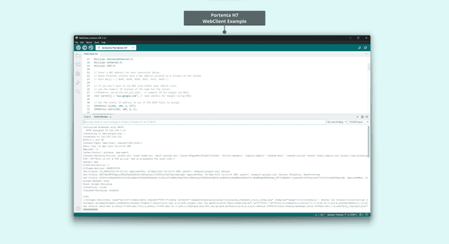
The WebClient example below can be used to test Ethernet connectivity for Portenta C33:
1#include <EthernetC33.h>2
3// if you don't want to use DNS (and reduce your sketch size)4// use the numeric IP instead of the name for the server:5//IPAddress server(74,125,232,128); // numeric IP for Google (no DNS)6char server[] = "www.google.com"; // name address for Google (using DNS)7
8// Set the static IP address to use if the DHCP fails to assign9IPAddress ip(10, 130, 22, 84);10
11// Initialize the Ethernet client library12// with the IP address and port of the server13// that you want to connect to (port 80 is default for HTTP):14EthernetClient client;15
16void setup() {17 // Open serial communications and wait for port to open:18 Serial.begin(115200);19
20 while (!Serial) {21 ; // wait for serial port to connect. Needed for native USB port only22 }23
24 bool use_dns = true;25
26 // start the Ethernet connection:27 if (Ethernet.begin() == 0) {28 Serial.println("Failed to configure Ethernet using DHCP");29 // try to configure using IP address instead of DHCP:30 // IN THAT CASE YOU SHOULD CONFIGURE manually THE DNS or USE the IPAddress Server variable above31 // that is what is automatically done here...32 Ethernet.begin(ip);33 use_dns = false;34 }35 // give the Ethernet shield a second to initialize:36 delay(2000);37 Serial.println("connecting...");38
39 Serial.print("Your DNS server is: ");40 Serial.println(Ethernet.dnsServerIP());41
42 bool connect_result = false;43
44 if(use_dns) {45 connect_result = client.connect(server, 80);46 }47 else {48 connect_result = client.connect(IPAddress(74,125,232,128), 80);49 }50
51 // if you get a connection, report back via serial:52 if (client.connect(server, 80)) {53 Serial.println("connected");54 // Make a HTTP request:55 client.println("GET /search?q=arduino HTTP/1.1");56 client.println("Host: www.google.com");57 client.println("Connection: close");58 client.println();59 } else {60 // if you didn't get a connection to the server:61 Serial.println("connection failed");62 }63}64
65/* just wrap the received data up to 80 columns in the serial print*/66void read_request() {67 uint32_t received_data_num = 0;68 while (client.available()) {69 /* actual data reception */70 char c = client.read();71 /* print data to serial port */72 Serial.print(c);73 /* wrap data to 80 columns*/74 received_data_num++;75 if(received_data_num % 80 == 0) {76 Serial.println();77 }78 }79}80
81void loop() {82
83 read_request();84
85 // if the server's disconnected, stop the client:86 if (!client.connected()) {87 Serial.println();88 Serial.println("disconnecting.");89 client.stop();90
91 // do nothing forevermore:92 while (true);93 }94}After establishing the connection, similar outcomes will be shown in the Serial Monitor, as depicted in the following image:
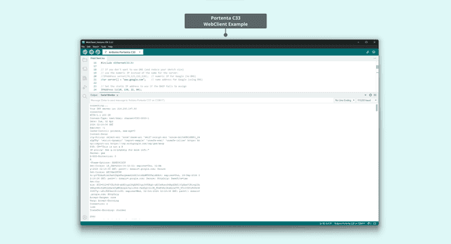
Wi-Fi® & Bluetooth®
The Portenta Mid Carrier can be complemented with the wireless capabilities of Portenta models like the X8, H7, or C33. It enhances the use of Wi-Fi® and Bluetooth® technologies integrated into these boards. Activating these wireless features allows them to synergize with the carrier's core functionalities, creating a more versatile and rich solution for various projects.
This integration expands the range of possible applications for the Portenta Mid Carrier, allowing developers to use wireless communications in their projects. Combining the carrier's onboard capabilities with these wireless technologies makes the Portenta Mid Carrier a valuable asset for developers seeking flexible and powerful connectivity options.
For detailed information on the connectivity features of each Portenta model, please refer to their specific documentation:
- For Portenta X8 connectivity details, see Wi-Fi® configuration and Bluetooth®
- For Portenta H7 connectivity information, visit the Wi-Fi® access point and BLE connectivity
- For Portenta C33, refer to the User Manual for Wi-Fi® and Bluetooth® details
Pins
The Portenta Mid Carrier is a versatile platform, and a significant feature of this carrier is its extensive pin availability. These pins provide a range of functionalities, including power, I/Os, communication, and more.
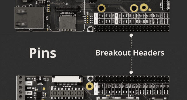
This section will examine the Breakout and PCIe breakout header of the Portenta Mid Carrier. These headers are integral to the carrier's interfacing capabilities, providing diverse connectivity options for various applications.
Portenta Mid Carrier Breakout Header (J14 - J15)
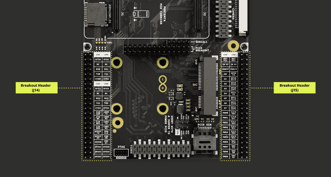
The following table constitutes details for the J14 Breakout Header:
| Pin Number | Silkscreen Pin | Power Net | Portenta Standard Pin | High-Density Pin |
|---|---|---|---|---|
| 1 | GND | Ground | GND | J1-22, J1-31, J1-42, J1-47, J1-54, J2-24, J2-33, J2-44, J2-57, J2-70 |
| 2 | GND | Ground | GND | J1-22, J1-31, J1-42, J1-47, J1-54, J2-24, J2-33, J2-44, J2-57, J2-70 |
| 3 | RTS0 | SERIAL0_RTS | J1-38 | |
| 4 | RTS1 | SERIAL1_RTS | J1-37 | |
| 5 | NC | NC | ||
| 6 | NC | NC | ||
| 7 | RX0 | SERIAL0_RX | J1-36 | |
| 8 | RX1 | SERIAL1_RX | J1-35 | |
| 9 | TX0 | SERIAL0_TX | J1-34 | |
| 10 | TX1 | SERIAL1_TX | J1-33 | |
| 11 | CTS0 | SERIAL0_CTS | J1-40 | |
| 12 | CTS1 | SERIAL1_CTS | J1-39 | |
| 13 | GND | Ground | GND | J1-22, J1-31, J1-42, J1-47, J1-54, J2-24, J2-33, J2-44, J2-57, J2-70 |
| 14 | GND | Ground | GND | J1-22, J1-31, J1-42, J1-47, J1-54, J2-24, J2-33, J2-44, J2-57, J2-70 |
| 15 | RTS2 | SERIAL2_RTS | J2-30 | |
| 16 | RTS3 | SERIAL3_RTS | J2-29 | |
| 17 | NC | NC | ||
| 18 | NC | NC | ||
| 19 | RX2 | SERIAL2_RX | J2-28 | |
| 20 | RX3 | SERIAL3_RX | J2-27 | |
| 21 | TX2 | SERIAL2_TX | J2-26 | |
| 22 | TX3 | SERIAL3_TX | J2-25 | |
| 23 | CTS2 | SERIAL2_CTS | J2-32 | |
| 24 | CTS3 | SERIAL3_CTS | J2-31 | |
| 25 | I2S CLK | I2S_CK | J1-56 | |
| 26 | CAN0 TX | CAN0_TX | J1-50 | |
| 27 | I2S WS | I2S_WS | J1-58 | |
| 28 | CAN0 RX | CAN0_RX | J1-52 | |
| 29 | I2S SDI | I2S_SDI | J1-60 | |
| 30 | CAN1 TX | CAN1_TX | J1-49 | |
| 31 | I2S SDO | I2S_SDO | J1-62 | |
| 32 | CAN1 RX | CAN1_RX | J1-51 | |
| 33 | SPDIF TX | SPDIF_TX | J1-74 | |
| 34 | PDM CLK | PDM_CK | J1-66 | |
| 35 | SPDIF RX | SPDIF_RX | J1-76 | |
| 36 | PDM D0 | PDM_D0 | J1-68 | |
| 37 | GPIO0 | GPIO_0 | J2-46 | |
| 38 | PDM D1 | PDM_D1 | J1-70 | |
| 39 | GPIO1 | GPIO_1 | J2-48 | |
| 40 | GPIO6 | GPIO_6 | J2-58 | |
| 41 | GPIO2 | GPIO_2 | J2-50 | |
| 42 | GPIO5 | GPIO_5 | J2-56 | |
| 43 | GPIO3 | GPIO_3 | J2-52 | |
| 44 | GPIO4 | GPIO_4 | J2-54 |
The following table constitutes details for the J15 Breakout Header:
| Pin Number | Silkscreen Pin | Power Net | Portenta Standard Pin | High-Density Pin |
|---|---|---|---|---|
| 1 | GND | Ground | GND | J1-22, J1-31, J1-42, J1-47, J1-54, J2-24, J2-33, J2-44, J2-57, J2-70 |
| 2 | GND | Ground | GND | J1-22, J1-31, J1-42, J1-47, J1-54, J2-24, J2-33, J2-44, J2-57, J2-70 |
| 3 | VCC | +3V3 Portenta (Out) | VCC | J2-23, J2-34, J2-43, J2-69 |
| 4 | VCC | +3V3 Portenta (Out) | VCC | J2-23, J2-34, J2-43, J2-69 |
| 5 | VIN | +5V (In/Out) | VIN | J1-21, J1-32, J1-41, J1-48 |
| 6 | VIN | +5V (In/Out) | VIN | J1-21, J1-32, J1-41, J1-48 |
| 7 | VREFP | ANALOG_VREF_P | J2-71 | |
| 8 | VREFN | ANALOG_VREF_N | J2-72 | |
| 9 | A0 | ANALOG_A0 | J2-73 | |
| 10 | SPI0 CS | SPI0_CS | J2-53 | |
| 11 | A1 | ANALOG_A1 | J2-75 | |
| 12 | SPI0 SCLK | SPI0_CK | J2-37 | |
| 13 | A2 | ANALOG_A2 | J2-77 | |
| 14 | SPI0 CIPO | SPI0_MISO | J2-39 | |
| 15 | A3 | ANALOG_A3 | J2-79 | |
| 16 | SPI0 COPI | SPI0_MOSI | J2-41 | |
| 17 | A4 | ANALOG_A4 | J2-74 | |
| 18 | SPI1 CS | SPI1_CS | J2-36 | |
| 19 | A5 | ANALOG_A5 | J2-76 | |
| 20 | SPI1 SCLK | SPI1_CK | J2-38 | |
| 21 | A6 | ANALOG_A6 | J2-78 | |
| 22 | SPI1 CIPO | SPI1_MISO | J2-40 | |
| 23 | A7 | ANALOG_A7 | J2-80 | |
| 24 | SPI1 COPI | SPI1_MOSI | J2-42 | |
| 25 | PWM0 | PWM_0 | J2-59 | |
| 26 | I2C0 SDA | I2C0_SDA | J1-44 | |
| 27 | PWM1 | PWM_1 | J2-61 | |
| 28 | I2C0 SCL | I2C0_SCL | J1-46 | |
| 29 | PWM2 | PWM_2 | J2-63 | |
| 30 | I2C1 SDA | I2C1_SDA | J1-43 | |
| 31 | PWM3 | PWM_3 | J2-65 | |
| 32 | I2C1 SCL | I2C1_SCL | J1-45 | |
| 33 | PWM4 | PWM_4 | J2-67 | |
| 34 | I2C2 SDA | I2C2_SDA | J2-45 | |
| 35 | PWM5 | PWM_5 | J2-60 | |
| 36 | I2C2 SCL | I2C2_SCL | J2-47 | |
| 37 | PWM6 | PWM_6 | J2-62 | |
| 38 | SAI CLK | SAI_CK | J2-49 | |
| 39 | PWM7 | PWM_7 | J2-64 | |
| 40 | SAI FS | SAI_FS | J2-51 | |
| 41 | PWM8 | PWM_8 | J2-66 | |
| 42 | SAI D0 | SAI_D0 | J2-53 | |
| 43 | PWM9 | PWM_9 | J2-68 | |
| 44 | SAI D1 | SAI_D1 | J2-55 |
PCIe Breakout Header (J16)
| Pin Number | Silkscreen Pin | Power Net | Portenta Standard Pin | High-Density Pin | Pin Detail |
|---|---|---|---|---|---|
| 1 | N/A | PCIE_CK_P | J2-17 | ||
| 2 | N/A | PCIE_TX_P | J2-9 | ||
| 3 | N/A | PCIE_CK_N | J2-19 | ||
| 4 | N/A | PCIE_TX_N | J2-11 | ||
| 5 | N/A | PCIE_RX_N | J2-15 | ||
| 6 | N/A | Connected to pin 51 of mPCIE J8 connector | |||
| 7 | N/A | PCIE_RX_P | J2-13 | ||
| 8 | N/A | Connected to pin 49 of mPCIE J8 connector | |||
| 9 | N/A | PCIE_RST | J2-21 | Connected to pin 22 of mPCIE J8 connector | |
| 10 | N/A | Connected to pin 47 of mPCIE J8 connector | |||
| 11 | N/A | Connected to pin 19 of mPCIE J8 connector | |||
| 12 | N/A | Connected to pin 45 of mPCIE J8 connector | |||
| 13 | N/A | Connected to pin 17 of mPCIE J8 connector | |||
| 14 | N/A | Connected to pin 48 of mPCIE J8 connector | |||
| 15 | N/A | Connected to pin 16 of mPCIE J8 connector | |||
| 16 | N/A | Connected to pin 46 of mPCIE J8 connector | |||
| 17 | N/A | Connected to pin 6 of mPCIE J8 connector | |||
| 18 | N/A | Connected to pin 44 of mPCIE J8 connector | |||
| 19 | N/A | Connected to pin 5 of mPCIE J8 connector | |||
| 20 | N/A | Connected to pin 42 of mPCIE J8 connector | |||
| 21 | N/A | Connected to pin 3 of mPCIE J8 connector | |||
| 22 | N/A | Connected to pin 28 of mPCIE J8 connector | |||
| 23 | N/A | Connected to pin 1 of mPCIE J8 connector | |||
| 24 | N/A | Ground | GND | J1-22, J1-31, J1-42, J1-47, J1-54 J2-24, J2-33, J2-44, J2-57, J2-70 | |
| 25 | N/A | I2C0_SCL | J1-46 | ||
| 26 | N/A | Connected to pin 30 of mPCIE J8 connector | |||
| 27 | N/A | I2C0_SDA | J1-44 | ||
| 28 | N/A | Connected to pin 32 of mPCIE J8 connector |
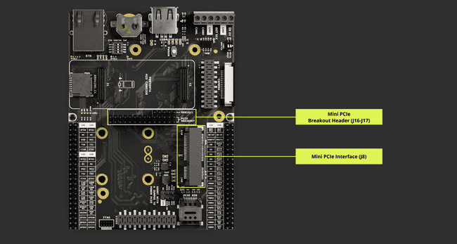
The mini PCIe breakout header also has sub-series pins (J17) detailed in the following table:
| Pin Number | Silkscreen Pin | Portenta Standard Pin | High-Density Pin | Pin Detail |
|---|---|---|---|---|
| 1 | N/A | SERIAL1_RX | J1-35 | Connected to pin 8 of J14 connector |
| 2 | N/A | SERIAL1_TX | J1-33 | Connected to pin 10 of J14 connector |
| 3 | N/A | SERIAL1_RTS | J1-37 | Connected to pin 4 of J14 connector |
| 4 | N/A | SERIAL1_CTS | J1-39 | Connected to pin 12 of J14 connector |
| 5 | N/A | GPIO_6 | J2-58 | Connected to pin 40 of J14 connector |
GPIO Pins
Understanding and managing your device's General-Purpose Input/Output (GPIO) pins can be crucial for many applications. The following script is designed to display all the GPIOs available on the breakout connector of the Portenta Mid Carrier paired with Portenta X8.
The Portenta.GPIO library, officially supported and compatible with the Portenta Mid Carrier and Portenta X8, can be found here.
The GPIO configuration register for the STM32 microcontroller is structured with various fields that control different aspects of GPIO functionality:
| 8 | 7 | 6 | 5 | 4 3 | 2 1 0 |
|---|---|---|---|---|---|
| PE | HYS | PUE | ODE | FSEL | DSE |
- PE (Pull Resistors Enable): Controls the use of pull resistors. 0 disables them, while 1 enables them.
- HYS (Hysteresis Enable Field): Sets the input type. 0 selects CMOS input, and 1 selects Schmitt input.
- PUE (Control IO ports PS): Determines the type of pull resistors used. 0 selects pull-down resistors, and 1 selects pull-up resistors.
- ODE (Open Drain Enable Field): Configures the pin for open-drain mode. 0 turns off, 1 enables.
- FSEL (Slew Rate Field): Controls the slew rate. 0X is slow, 1X is fast.
- DSE (Drive Strength Field): Adjusts the drive strength. Options range from X1 to X6, with varying levels of strength.
To control a desired GPIO within the Linux environment of the Portenta X8, the following GPIO chip formula can help get the required number designation:
1[(<GPIO group> -1) * 32] + <GPIO number>For example, PA0 is one available GPIO pin from Port A within i.MX8M Mini found with the Portenta X8. Its GPIO designation is defined as
GPIO1_IO07Applying the formula to the GPIO designation, the formula field is seen as follows:
1# Illustrative form2[(GPIO1 - 1) * 32] + IO073
4# Numeric form5[(1 - 1) * 32] + 7 = 7With this, it is possible to recognize that PA0, known as
GPIO1_IO077Each GPIO chip manages a specific range of GPIO numbers, facilitating organized and efficient access to the GPIO functionality of the STM32 microcontroller. The GPIO groups for the Portenta X8 are segmented in the following manner:
| GPIO Chip | Corresponding GPIO Number |
|---|---|
| gpiochip0 | GPIOs 0-31 |
| gpiochip1 | GPIOs 32-63 |
| gpiochip2 | GPIOs 64-95 |
| gpiochip3 | GPIOs 96-127 |
| gpiochip4 | GPIOs 128-159 |
| gpiochip5 | GPIOs 160-193 (H7 GPIOs) |
The STM32 microcontroller includes various GPIO ports, each with a specific set of pins. The enumeration of these GPIO ports is as follows:
- Port A: PA6, PA8, PA9, PA10, PA11, PA12
- Port B: PB1, PB5, PB6, PB10
- Port C: PC4, PC6, PC7, PC8
- Port D: PD0, PD1, PD3, PD4, PD5, PD6, PD15
- Port E: PE10, PE11
- Port F: PF3, PF4, PF5, PF6, PF7, PF8, PF9, PF11, PF12, PF13
Each pin is identified by its port and a unique port number. The following table shows the numeric designations of the GPIOs handled by the STM32 microcontroller.
| Port | Port Number | Port Name | Function / Role |
|---|---|---|---|
| Port A | |||
| 168 | PA6 | ADC_CH1 (A1) | |
| 189 | PA8 | PWM_6 | |
| 184 | PA9 | PWM_1 | |
| 185 | PA10 | PWM_2 | |
| 187 | PA11 | PWM_4 | |
| 191 | PA12 | PWM_8 | |
| Port B | |||
| 170 | PB1 | ADC_CH3 (A3) | |
| 178 | PB5 | FDCAN2_RX | |
| 177 | PB6 | FDCAN2_TX | |
| 186 | PB10 | PWM_3 | |
| Port C | |||
| 171 | PC4 | ADC_CH4 (A4) | |
| 190 | PC6 | PWM_7 | |
| 183 | PC7 | PWM_0 | |
| 192 | PC8 | PWM_9 | |
| Port D | |||
| 176 | PD0 | FDCAN1_RX | |
| 175 | PD1 | FDCAN1_TX | |
| 182 | PD3 | USART2_CTS | |
| 181 | PD4 | USART2_RTS | |
| 189 | PD5 | USART2_TX | |
| 180 | PD6 | USART2_RX | |
| 188 | PD15 | ||
| Port E | |||
| 165 | PE10 | GPIO_5 | |
| 166 | PE11 | GPIO_6 | |
| Port F | |||
| 162 | PF3 | GPIO_2 | |
| 163 | PF4 | GPIO_3 | |
| 174 | PF5 | ADC_CH7 (A7) | |
| 161 | PF6 | GPIO_1 | |
| 172 | PF7 | ADC_CH5 (A5) | |
| 160 | PF8 | GPIO_0 | |
| 173 | PF9 | ADC_CH6 (A6) | |
| 167 | PF11 | ADC_CH0 (A0) | |
| 164 | PF12 | GPIO_4 | |
| 169 | PF13 | ADC_CH2 (A2) |
The breakout header offers access directly to GPIOs:
| Pin Number | Silkscreen Pin | Portenta Standard Pin | High-Density Pin |
|---|---|---|---|
| 37 | GPIO0 | GPIO_0 | J2-46 |
| 39 | GPIO1 | GPIO_1 | J2-48 |
| 40 | GPIO6 | GPIO_6 | J2-58 |
| 41 | GPIO2 | GPIO_2 | J2-50 |
| 42 | GPIO5 | GPIO_5 | J2-56 |
| 43 | GPIO3 | GPIO_3 | J2-52 |
| 44 | GPIO4 | GPIO_4 | J2-54 |
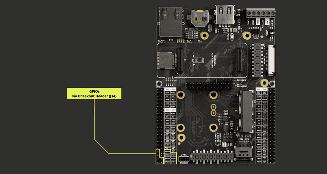
Using Linux With Shell
The General Purpose Input/Output (GPIO) pins of the Portenta X8 can be managed using the ADB shell. Initially, you need to gain administrative access to the Portenta X8's shell. This is a crucial step to modify settings that require higher privileges.
Once you have administrative access, use the following command to make a specific GPIO available. Here, we are using GPIO3 as an example, which corresponds to 163:
1echo 163 > /sys/class/gpio/exportTo check which GPIOs are ready for use, execute this command:
1ls /sys/class/gpioIt lists all the GPIOs that the system has initialized. For more details about GPIO3 (or 163), which you just made available, run:
1ls /sys/class/gpio/gpio163After exporting GPIO3, you can set it up as an Input or Output. The command below is used to define the pin's mode. Replace
<I/O>inout1echo <I/O> >/sys/class/gpio/gpio163/directionFor this example, the
<I/O>out1echo out >/sys/class/gpio/gpio163/directionThe
cat1cat /sys/class/gpio/gpio163/directionOnce the GPIO is set as an output, you can change its state. To set the pin to High (active), use
10To set to High:
1echo 1 >/sys/class/gpio/gpio163/valueTo set to Low:
1echo 0 >/sys/class/gpio/gpio163/valueAfter using the GPIO, it is an excellent practice to unexport it, which removes it from the userspace and prevents accidental changes. The following command allows making such change:
1echo 163 >/sys/class/gpio/unexportTo ensure the GPIO has been unexported properly and is no longer available for use, run:
1ls /sys/class/gpioBy following these steps, you can manage the GPIO settings on the Portenta X8, from gaining administrative access to safely unexporting the GPIO after use with the carrier.
Using Linux With Library
The General-Purpose Input/Output (GPIO) features of the Portenta X8 can be effectively controlled using the python-periphery. The library offers a user-friendly way to manage GPIOs, which is especially useful when integrating GPIO control into Python® scripts.
The Portenta.GPIO library will be available soon to offer dedicated yet simplified processes to control all available GPIOs within the Portenta Mid Carrier.
The example below demonstrates how to check the status of all GPIOs on a Portenta X8 mounted on the Portenta Mid Carrier. This script is part of the
container, where the necessary environment is already set up.x8-devel
The following conditions are recommended to ensure the hardware is correctly configured for testing GPIO controls:
Attach the Portenta-X8 securely to the Portenta Mid Carrier, ensuring the High-Density connectors are correctly connected.
Each GPIO on the Portenta Mid Carrier is versatile, safely accommodating input voltages from 0.0 V to 3.3 V. This range ensures compatibility with various sensors and devices.
To maintain stable and predictable behavior, internal pull-ups are enabled by default on all input pins, meaning they will read as high (3.3 V) unless actively driven low.
When all conditions are set and in place, access the Portenta X8's shell with administrative privileges:
1adb shell2sudo su -Enter the password
fio1docker exec -it x8-devel shNavigate to the directory with the
gpios.py1cd root/examples/Before running the example script, and to ensure the container environment is adequately configured, please use the following command:
1export $(grep -v '^#' /run/arduino_hw_info.env | xargs)Run the
gpios.py1python gpios.pyThe code below is compatible with the Portenta Mid carrier, as the Portenta X8 is the core used to control the GPIOs over High-Density pins:
1#!/usr/bin/env python32
3# Read all gpios4
5# A simple script to print all the gpios on6# the corresponding connector of the Breakout carrier7
8# Circuit:9# * Place Portenta-X8 on a Breakout carrier10# * All gpios accepts 0.0v - 3.3v input range11# * Internal pull up are enabled by default on all input pins12
13# created 18 March 202214# by Massimo Pennazio15
16import os17from periphery import GPIO18
19if os.environ['CARRIER_NAME'] != "breakout":20 print("This script requires Breakout carrier")21 exit(1)22
23gpio0 = GPIO("/dev/gpiochip5", 0, "in")24gpio1 = GPIO("/dev/gpiochip5", 1, "in")25gpio2 = GPIO("/dev/gpiochip5", 2, "in")26gpio3 = GPIO("/dev/gpiochip5", 3, "in")27gpio4 = GPIO("/dev/gpiochip5", 4, "in")28gpio5 = GPIO("/dev/gpiochip5", 5, "in")29gpio6 = GPIO("/dev/gpiochip5", 6, "in")30
31value0 = int(gpio0.read())32value1 = int(gpio1.read())33value2 = int(gpio2.read())34value3 = int(gpio3.read())35value4 = int(gpio4.read())36value5 = int(gpio5.read())37value6 = int(gpio6.read())38
39print("GPIO0 = %d" % value0)40print("GPIO1 = %d" % value1)41print("GPIO2 = %d" % value2)42print("GPIO3 = %d" % value3)43print("GPIO4 = %d" % value4)44print("GPIO5 = %d" % value5)45print("GPIO6 = %d" % value6)This script consolidates and displays the status of all GPIOs, saving time and reducing error risk.
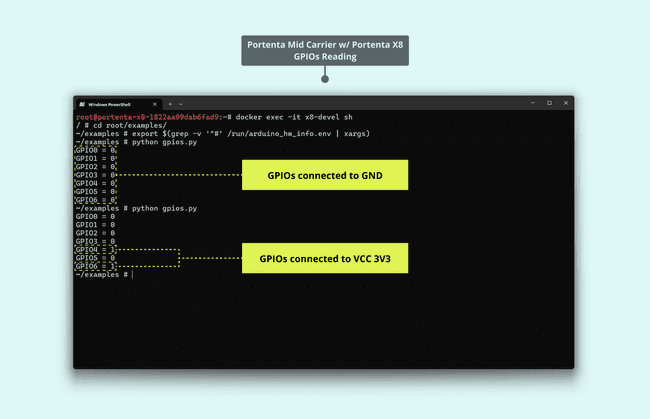
It is beneficial for debugging, prototyping, or setting up new projects on the Portenta Mid Carrier. Such considerations involve:
Avoid manually checking each pin by having a consolidated overview of all GPIOs' statuses.
By staying within the specified voltage range, you ensure the longevity of your device and prevent potential damages.
With the default pull-ups, you can be confident in your readings, knowing unintentional fluctuations are minimized.
The Portenta.GPIO library will soon be released to add compatibility to the Portenta Mid Carrier, providing a dedicated and streamlined approach to managing all GPIOs on the carrier.
For a quick overview of available GPIOs on the Portenta X8, this shell command can be used:
1cat /sys/kernel/debug/gpioThis command provides a convenient way to view the GPIO setup and status directly from the shell.
Analog Pins
The Portenta Mid Carrier's breakout header connector includes analog channels, providing access to the analog pins
A0A1A2A3A4A5A6A7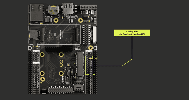
The table below details the pin assignments for these analog channels:
| Pin Number | Silkscreen Pin | Power Net | Portenta Standard Pin | High-Density Pin |
|---|---|---|---|---|
| 7 | VREFP | ANALOG_VREF_P | J2-71 | |
| 8 | VREFN | ANALOG_VREF_N | J2-72 | |
| 9 | A0 | ANALOG_A0 | J2-73 | |
| 11 | A1 | ANALOG_A1 | J2-75 | |
| 13 | A2 | ANALOG_A2 | J2-77 | |
| 15 | A3 | ANALOG_A3 | J2-79 | |
| 17 | A4 | ANALOG_A4 | J2-74 | |
| 19 | A5 | ANALOG_A5 | J2-76 | |
| 21 | A6 | ANALOG_A6 | J2-78 | |
| 23 | A7 | ANALOG_A7 | J2-80 |
To interact with these analog input pins, you can use the built-in functionalities of the Arduino programming language, precisely the
function, available in the Arduino IDE.analogRead()
To locate these analog pins on the board, please consult the board pinout section of the user manual.
Using Linux
When using the Portenta X8, you can measure voltage within a range of 0 to 65535, which correlates to a real-world voltage range of 0 to 3.3 V. To obtain this voltage reading, you can use the following command within the ADB shell:
1cat /sys/bus/iio/devices/iio\:device0/in_voltage<adc_pin>_rawHere,
<adc_pin>A01cat /sys/bus/iio/devices/iio\:device0/in_voltage0_rawFor those working with Python®, you can incorporate this command into your script as demonstrated in the example script below:
1def read_adc_value(adc_pin):2 try:3 with open(f'/sys/bus/iio/devices/iio:device0/in_voltage{adc_pin}_raw', 'r') as file:4 return int(file.read().strip())5 except FileNotFoundError:6 print(f"ADC pin {adc_pin} not found!")7 return None8
9if __name__ == "__main__":10 adc_pin = input("Enter ADC pin number: ")11 value = read_adc_value(adc_pin)12
13 if value is not None:14 print(f"Value from ADC pin {adc_pin}: {value}")15
16 # Mapping between 0-3.3 V17 new_value = (float) (value/65535)*3.318 print(f"Value mapped between 0-3.3 V: {new_value}")Using Arduino IDE
The example code below, designed for the Portenta H7, exemplifies the voltage readings obtained from a potentiometer connected to
A01// Define the potentiometer pin and variable to store its value2int potentiometerPin = A0;3int potentiometerValue = 0;4
5void setup() {6 // Initialize Serial communication7 Serial.begin(9600);8}9
10void loop() {11 // Read the voltage value from the potentiometer12 potentiometerValue = analogRead(potentiometerPin);13
14 // Print the potentiometer voltage value to the Serial Monitor15 Serial.print("- Potentiometer voltage value: ");16 Serial.println(potentiometerValue);17
18 // Wait for 1000 milliseconds19 delay(1000);20}The following example can be used with the Portenta C33:
1#include "analogWave.h" // Include the library for analog waveform generation2
3analogWave wave(DAC); // Create an instance of the analogWave class, using the DAC pin4
5int freq = 10; // in hertz, change accordingly6
7void setup() {8 Serial.begin(115200); // Initialize serial communication at a baud rate of 1152009 wave.sine(freq); // Generate a sine wave with the initial frequency10}11
12void loop() {13 // Read an analog value from pin XX and map it to a frequency range14 freq = map(analogRead(XX), 0, 1024, 0, 10000);15
16 // Print the updated frequency to the serial monitor17 Serial.println("Frequency is now " + String(freq) + " hz");18
19 wave.freq(freq); // Set the frequency of the waveform generator to the updated value20 delay(1000); // Delay for one second before repeating21}PWM Pins
The Portenta Mid Carrier has ten digital pins with PWM functionality, mapped as follows:
| Pin Number | Silkscreen Pin | Power Net | Portenta Standard Pin | High-Density Pin |
|---|---|---|---|---|
| 25 | PWM0 | - | PWM_0 | J2-59 |
| 27 | PWM1 | - | PWM_1 | J2-61 |
| 29 | PWM2 | - | PWM_2 | J2-63 |
| 31 | PWM3 | - | PWM_3 | J2-65 |
| 33 | PWM4 | - | PWM_4 | J2-67 |
| 35 | PWM5 | - | PWM_5 | J2-60 |
| 37 | PWM6 | - | PWM_6 | J2-62 |
| 39 | PWM7 | - | PWM_7 | J2-64 |
| 41 | PWM8 | - | PWM_8 | J2-66 |
| 43 | PWM9 | - | PWM_9 | J2-68 |
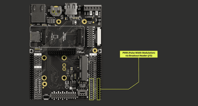
Please refer to the board pinout section of the user manual to find them on the board. All these pins must be configured on the corresponding Portenta.
Using Linux
The following Python® script is designed to control the brightness of a device, such as an LED, by varying the duty cycle of a PWM signal in a Linux environment on Portenta X8.
The script sets up the PWM channel, defines its period, and then, within a loop, modulates the brightness by adjusting the duty cycle. Consider the script below as an example:
1#!/usr/bin/env python32
3import time4import subprocess5
6# Define the PWM chip, channel, and other parameters7PWM_CHIP = 08PWM_CHANNEL = 9 # Replace with the correct channel if necessary9BASE_PATH = f"/sys/class/pwm/pwmchip{PWM_CHIP}/pwm{PWM_CHANNEL}"10PERIOD = 1000000000 # 1 second in nanoseconds11FADE_DURATION = 0.03 # 30 milliseconds12
13# Define brightness and fade amount variables14brightness = 015fadeAmount = 5 * (PERIOD // 255) # Scale fadeAmount for our period16
17def setup_pwm():18 subprocess.run(f"echo {PWM_CHANNEL} | sudo tee /sys/class/pwm/pwmchip{PWM_CHIP}/export", shell=True)19 subprocess.run(f"echo {PERIOD} | sudo tee {BASE_PATH}/period", shell=True)20 subprocess.run(f"echo 0 | sudo tee {BASE_PATH}/duty_cycle", shell=True)21 subprocess.run(f"echo 1 | sudo tee {BASE_PATH}/enable", shell=True)22
23def set_pwm_brightness(brightness_value):24 duty_cycle = brightness_value * (PERIOD // 255)25 subprocess.run(f"echo {duty_cycle} | sudo tee {BASE_PATH}/duty_cycle", shell=True)26
27if __name__ == "__main__":28 setup_pwm()29 try:30 while True:31 set_pwm_brightness(brightness)32 brightness += fadeAmount33 if brightness <= 0 or brightness >= 255:34 fadeAmount = -fadeAmount35 time.sleep(FADE_DURATION)36 except KeyboardInterrupt:37 print("Exiting")Using Arduino IDE
The [
analogWrite()In the example code below, a PWM-capable pin is used to adjust the luminosity of an LED that is attached to it:
1const int ledPin = <PWM_X>; // Use a pin that supports PWM2
3void setup() {4 pinMode(ledPin, OUTPUT); // Configure the pin as OUTPUT5}6
7void loop() {8 // Increase brightness9 for (int brightness = 0; brightness <= 255; brightness++) {10 analogWrite(ledPin, brightness);11 delay(10);12 }13
14 // Decrease brightness15 for (int brightness = 255; brightness >= 0; brightness--) {16 analogWrite(ledPin, brightness);17 delay(10);18 }19}JTAG Pins (J3)
The Portenta Mid Carrier features a built-in JTAG interface to get detailed insight and log the elaborate development details. It provides hardware debugging, offering real-time observation. Through the JTAG pins, users can debug and program, guaranteeing accurate and optimal device performance.
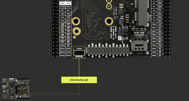
The pins used for the JTAG debug port on the Portenta Mid Carrier are the following:
| Pin Number | Silkscreen Pin | Power Net | Portenta Standard Pin | High-Density Pin |
|---|---|---|---|---|
| 1 | N/A | +3V3 Portenta (Out) | VCC | J2-23, J2-34, J2-43, J2-69 |
| 2 | N/A | JTAG_SWD | J1-75 | |
| 3 | N/A | Ground | GND | J1-22, J1-31, J1-42, J1-47, J1-54, J2-24, J2-33, J2-44, J2-57, J2-70 |
| 4 | N/A | JTAG_SCK | J1-77 | |
| 5 | N/A | Ground | GND | J1-22, J1-31, J1-42, J1-47, J1-54, J2-24, J2-33, J2-44, J2-57, J2-70 |
| 6 | N/A | JTAG_SWO | J1-79 | |
| 7 | NC | NC | NC | |
| 8 | N/A | JTAG_TDI | J1-78 | |
| 9 | N/A | JTAG_TRST | J1-80 | |
| 10 | N/A | JTAG_RST | J1-73 |
For further guidance on managing and using the debugging process, the following resources may be of assistance:
- Debugging with the Arduino IDE 2
- Debugging Fundamentals
- Debugging with Lauterbach TRACE32 GDB Front-End Debugger
Understanding Device Tree Blobs (DTB) Overlays
Device Tree Blobs (DTB) And DTB Overlays
In embedded systems, a key concept used by U-boot and the Linux kernel is the Device Tree Blobs (DTB). This is a method for detailing the hardware configuration of a board. The idea is to have a standard format that works across various board types, providing consistency and compatibility.
Consider these board platforms, such as carriers, to which you can attach different peripherals, like sensors or accelerometers. DTB makes it easier to manage these connections, offering flexibility for adding or removing components.
DTB overlays are an extension of this concept. They allow the hardware configuration to be modular, breaking it into smaller files. Each file represents a specific peripheral or feature. When the system boots, these overlays are combined into a single DTB in the memory, enabling customizable configurations. However, modifying the hardware setup requires a system reboot for stability.
Handling DTB Overlays
The following steps may help you adapt the DTB overlays for your Portenta X8 to support diverse hardware and devices.
Custom DTB Overlays
There may be situations where the existing DTB overlays do not meet your specific needs. In such cases, you can create custom DTB overlays. They are derived from source files called DTS files. With the respective experience, you can modify these DTS files and compile them into unique overlays customized to particular requirements.
Automated Load And Carrier Detection
U-boot can automatically select appropriate DTB overlays based on the detected carrier board, like the Portenta Mid Carrier. This detection can be hardware-based or involve reading an ID from an EEPROM.
For example, with a Portenta-X8 on a Portenta Mid Carrier, specific settings can be observed and modified through shell commands. U-boot sets these during the boot process in a step known as auto carrier detection. These settings are temporary and reset after a reboot unless you use the
carrier_custom11fw_printenv overlays2overlays=ov_som_lbee5kl1dx ov_som_x8h7 ov_carrier_xxxx3
4fw_printenv carrier_name5carrier_name=xxxx6
7fw_printenv is_on_carrier8is_on_carrier=yes9
10fw_setenv carrier_custom 1This serves as an escape mechanism to enable user-based configurations.
Hardware Configuration Layers
Hardware configuration is organized into layers:
- Layer 0: System on Module (SoM), prefixed with
.ov_som_ - Layer 1: Carrier boards, prefixed with
.ov_carrier_ - Layer 2: Cameras, for example, usually concatenate the carrier name and the element name or functionality.
EEPROMs storing identification IDs are usually found on Layer 1 and communicate via I2C1. Some add-ons may include EEPROMs following the respective standard accessible via a compatible protocol.
Overlays add specific functionalities. For instance:
: Adds Wi-Fi®ov_som_lbee5kl1dx
: Adds the H7 external microcontrollerov_som_x8h7
Without a recognized carrier, with the Portenta X8 as the main board, the system defaults to the first two overlays.
Distinction Between System And Hardware Configuration
It is vital to understand the difference between system configuration (like user setup and Wi-Fi® passwords) and hardware configuration, defined via the device tree. Custom device tree overlays are restricted to ensure system integrity and security in a production environment.
Communication
The Portenta Mid Carrier amplifies the Portenta core board's connectivity options by providing support for multiple communication standards, including Serial Peripheral Interface (SPI), Inter-Integrated Circuit (I2C), Universal Asynchronous Receiver-Transmitter (UART), JTAG interface, and MIPI, which is specifically adapted for use with the Portenta X8 camera. Detailed information on these communication protocols is provided in this section.
Dedicated connectors for each communication protocol are available on the Portenta Mid Carrier for ease of use. These connectors are readily accessible through the breakout male header, easing connection with various devices, peripherals, and sensors.
SPI
The Portenta Mid Carrier offers two SPI communication ports, designated SPI0 and SPI1. These ports are linked via High-Density connectors to the breakout male header.
This configuration helps transfer data between the board and other devices compatible with SPI. The Portenta Mid Carrier uses specific pins for SPI protocol, which are outlined in the table below:
| Pin Number | Silkscreen Pin | Power Net | Portenta Standard Pin | High-Density Pin |
|---|---|---|---|---|
| 10 | SPI0 CS | SPI0_CS | J2-53 | |
| 12 | SPI0 SCLK | SPI0_CK | J2-37 | |
| 14 | SPI0 CIPO | SPI0_MISO | J2-39 | |
| 16 | SPI0 COPI | SPI0_MOSI | J2-41 | |
| 18 | SPI1 CS | SPI1_CS | J2-36 | |
| 20 | SPI1 SCLK | SPI1_CK | J2-38 | |
| 22 | SPI1 CIPO | SPI1_MISO | J2-40 | |
| 24 | SPI1 COPI | SPI1_MOSI | J2-42 |
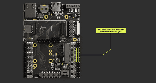
Please refer to the board pinout section of the user manual to find them on the board.
Using Linux
With root privileges, enter the following commands for the Portenta X8. To enable the SPI device interface on the Portenta X8, load the spidev module using the following:
1sudo modprobe spidevEnable the
spidev1echo "spidev" | sudo tee > /etc/modules-load.d/spidev.conf2sudo systemctl rebootTo configure a service named
my_spi_service/dev/spidev0.01services:2 my_spi_service:3 devices:4 - '/dev/spidev0.0'Such service configuration, for example, is made within the docker-compose.yml file.
I2S
I2S stands for Inter-IC Sound and is an electrical serial bus interface standard for connecting digital audio devices.
The interface operates with three main signals:
- SCK (Serial Clock) or BCLK: This clock signal synchronizes the data transmission.
- WS (Word Select) or FS (Frame Select): This signal indicates whether the data is for the Right or Left audio channel.
- SD (Serial Data): This line carries the transmitted audio data.
In an I2S system, one device is a Controller, generating the
SCKWSWhile one device functions as a Controller, others are set to Peripheral mode. The audio data can range from 4 to 32 bits per sample, with the understanding that higher sample rates and bit depths can yield better audio quality.
For the I2S communication on the Portenta Mid Carrier, the following pins are designated:
| Pin Number | Silkscreen Pin | Power Net | Portenta Standard Pin | High-Density Pin |
|---|---|---|---|---|
| 25 | I2S CLK | I2S_CK | J1-56 | |
| 27 | I2S WS | I2S_WS | J1-58 | |
| 29 | I2S SDI | I2S_SDI | J1-60 | |
| 31 | I2S SDO | I2S_SDO | J1-62 |
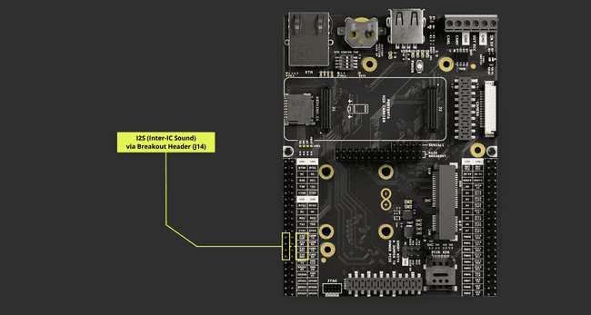
SAI - Serial Audio Interface
Serial Audio Interface (SAI) is a protocol for transmitting audio data between digital devices. It is more flexible than the I2S standard, allowing for different audio data formats and configurations. The following are the data lines that the carrier utilizes for SAI:
- D0: The main data line for sending or receiving audio data.
- CK (BCLK): The Bit Clock line controls the timing for sending or receiving each bit of audio data.
- FS: Frame Sync signal indicates the start of an audio data frame and is often used to switch between channels in stereo audio streams.
The SAI protocol can work synchronously and asynchronously, making it versatile enough to handle complex audio applications, such as systems requiring multiple audio channels or specific audio formats.
SAI's adaptability makes it suitable for elaborate audio processing tasks and use in systems requiring more complex configurations.
For the SAI communication on the Portenta Mid Carrier, the assigned pins are:
| Pin Number | Silkscreen Pin | Power Net | Portenta Standard Pin | High-Density Pin |
|---|---|---|---|---|
| 38 | SAI CLK | SAI_CK | J2-49 | |
| 40 | SAI FS | SAI_FS | J2-51 | |
| 42 | SAI D0 | SAI_D0 | J2-53 | |
| 44 | SAI D1 | SAI_D1 | J2-55 |
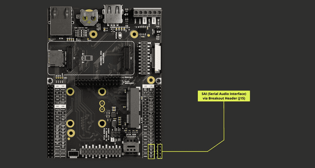
I2C
The Portenta Mid Carrier provides I2C communication, allowing data exchange with I2C-compatible devices. It uses specific pins for I2C protocol, detailed below:
| Pin Number | Silkscreen Pin | Power Net | Portenta Standard Pin | High-Density Pin |
|---|---|---|---|---|
| 26 | I2C0 SDA | I2C0_SDA | J1-44 | |
| 28 | I2C0 SCL | I2C0_SCL | J1-46 | |
| 30 | I2C1 SDA | I2C1_SDA | J1-43 | |
| 32 | I2C1 SCL | I2C1_SCL | J1-45 | |
| 34 | I2C2 SDA | I2C2_SDA | J2-45 | |
| 36 | I2C2 SCL | I2C2_SCL | J2-47 |
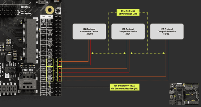
Refer to the user manual's pinout section for pin locations.
Using Linux
With administrative (root) privileges on the Portenta X8, the following shell commands are applicable:
1sudo modprobe i2c-devThe following command sequence activates the I2C device interface on the Portenta X8. To integrate the
i2c-dev1echo "i2c-dev" | sudo tee > /etc/modules-load.d/i2c-dev.conf2sudo systemctl rebootThese commands ensure the I2C device interface is enabled and properly set up in the system. The following section sets up I2C services by defining under
my_i2c_service1services:2 my_i2c_service:3 devices:4 - `/dev/i2c-0`5 - `/dev/i2c-1`6 - `/dev/i2c-2`7 - `/dev/i2c-3`All I2C services can be added from 0 to 3 or as specific services if desired.
The Portenta Mid Carrier fearures three I2C ports accessible via ADB shell. The following list shows the corresponding I2C bus for I2C port connected:
| Physical I2C Port | I2C Bus Designation |
|---|---|
| I2C0 | 2 |
| I2C1 | 1 |
| I2C2 | 3 |
Within the Portenta X8 shell, you can use specific commands to test I2C communication with compatible devices quickly. The command below lists all the connected I2C devices:
1i2cdetect -y <I2C bus>To interface with a specific I2C device and retrieve information, the command format is:
1i2cget -y <I2C bus> <device address> <register address>An example command format would be as follows:
1# i2cdetect -y <I2C bus>2i2cdetect -y 23
4# i2cget -y <I2C bus> <device address> <register address>5i2cget -y 2 0x77 0xD0Suppose you have a BME280 sensor connected to the I2C0 and used the above commands. In that case, the Portenta X8 should return similar results as in the image below:
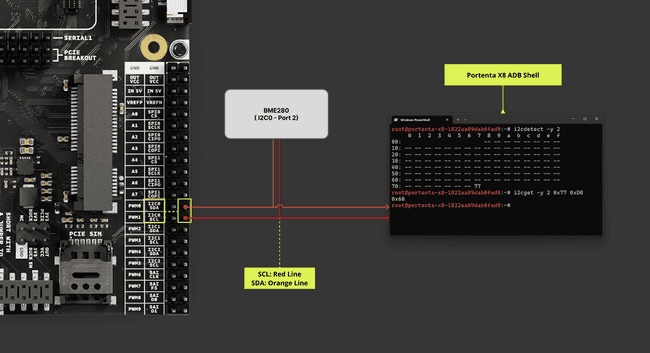
Below are simple examples of implementing I2C with the Portenta X8 and Portenta Mid Carrier. It is shown as an example of implementation within Python®.
Here, the SMBus (System Management Bus) communication, with SMBus-compatible libraries, is established with the device on
/dev/i2c-31from smbus2 import SMBus2
3# Connect to /dev/i2c-34bus = SMBus(3)5b = bus.read_byte_data(80, 0)6print(b)The following code initializes the I2C bus using the smbus2 library and reads multiple bytes from the device. The
read_i2c_block_data1from smbus2 import SMBus2
3# Initialize the I2C bus4bus = SMBus(3) # 3 indicates /dev/i2c-35
6device_address = 0x17num_bytes = 28
9# Read from the I2C device10data = bus.read_i2c_block_data(device_address, 0, num_bytes) # Starting address is 0 to read from11
12# Now data is a list of bytes13for byte in data:14 print(byte)The following code shows how to write data to an I2C device using the smbus2 library. A data byte (
valuedevice_address1from smbus2 import SMBus2
3# Initialize the I2C bus4bus = SMBus(3) # 3 indicates /dev/i2c-35
6device_address = 0x17instruction = 0x008value = 0xFF9
10# Write to the I2C device11bus.write_byte_data(device_address, instruction, value)In the following code, the python-periphery library interacts with the I2C device. This is useful if a broad spectrum of protocols are required within the same script. The
I2C.transfer()A byte is read from the EEPROM at address
0x500x1001from periphery import I2C2
3# Open i2c-0 controller4i2c = I2C("/dev/i2c-3")5
6# Read byte at address 0x100 of EEPROM at 0x507msgs = [I2C.Message([0x01, 0x00]), I2C.Message([0x00], read=True)]8i2c.transfer(0x50, msgs)9print("0x100: 0x{:02x}".format(msgs[1].data[0]))10
11i2c.close()To go a step further, setting up a Docker container for capturing data from the BME280 sensor through the I2C0 channel is one implementation example. This configuration uses SMBus-compatible libraries and the RPi.bme280 library, which conveniently includes the necessary sensor calibration routines. The connection setup between the BME280 sensor and the Portenta Mid Carrier is outlined as follows:
| Portenta Mid Carrier w/ Portenta X8 | BME280 |
|---|---|
| VCC | VIN |
| GND | GND |
| I2C0 SDA | SDI |
| I2C0 SCL | SCK |
For instructions on deploying a custom Docker container on the Portenta board, please see the detailed guide in the "Deploy a Custom Container with Portenta X8 Manager" tutorial.
Next, download the docker files from here and extract them to a directory of your choice within the Portenta X8. To build the Docker image required for establishing a connection and reading data from the BME280 sensor, use the following command:
1sudo docker build . -t bme28After the build is complete, you can run the container. Use the command below to start the container, which will then display results similar to the image shown:
1sudo docker compose up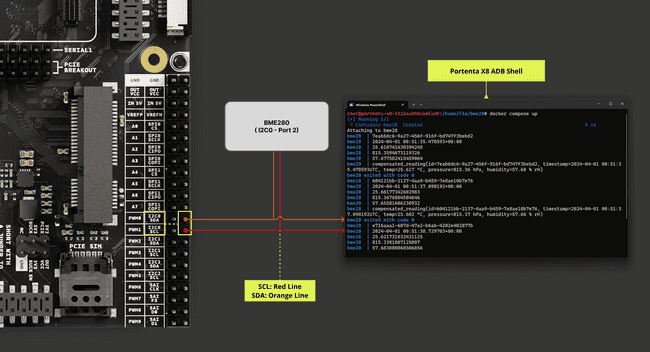
Using Arduino IDE
To enable I2C communication using the Portenta H7 or C33, begin by including the
library at the top of your sketch. This library offers a range of functions tailored for I2C communication:Wire
1#include <Wire.h>In the
setup()1// Initialize the I2C communication2Wire.begin();The following commands are available to transmit or write with an I2C-compatible device.
1// Replace with the target device's I2C address2byte deviceAddress = 0x1;3
4// Replace with the appropriate instruction byte5byte instruction = 0x00;6
7// Replace with the value to send8byte value = 0xFF;9
10// Begin transmission to the target device11Wire.beginTransmission(deviceAddress);12
13// Send the instruction byte14Wire.write(instruction);15
16// Send the value17Wire.write(value);18
19// End transmission20Wire.endTransmission();The following commands are available to request or read with an I2C-compatible device.
1// The target device's I2C address2byte deviceAddress = 0x1;3
4// The number of bytes to read5int numBytes = 2;6
7// Request data from the target device8Wire.requestFrom(deviceAddress, numBytes);9
10// Read while there is data available11while (Wire.available()) {12 byte data = Wire.read();13}For example, just as we have implemented with the Portenta X8, this setup can be replicated with the Portenta H7 and C33 models. In this context, the Adafruit BME280 library, which works in conjunction with the
library, is suitable for similar objectives of already implementing calibration functions.Wire
This library is accessible through the Library Manager in the Arduino IDE, and the
example from it will be used to obtain readings from the BME280 sensor. bme280test
After uploading the example onto the Portenta H7 paired with the Portenta Mid Carrier, you will notice the following behavior:
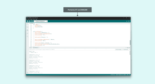
A similar outcome is expected when the setup involves the Portenta C33:
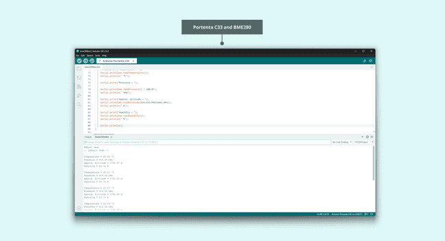
CAN Bus
The CAN bus, an acronym for Controller Area Network bus, is a robust communication system initially developed by Bosch® in the 1980s primarily for automotive applications. It enables microcontrollers and devices to communicate with each other without the need for a host computer. The protocol uses a multi-master design, allowing any network device to transmit data whenever the bus is available.
This decentralized approach is designed to maintain network integrity even if a component fails, making it exceptionally reliable in environments with significant electrical noise, such as vehicles. This reliability ensures consistent communication among the various electronic devices within such settings.
The Portenta Mid Carrier incorporates CAN bus functionality, featuring the TJA1049, a high-speed CAN FD transceiver module. This addition helps developers to integrate the dependable and efficient CAN bus communication protocol.
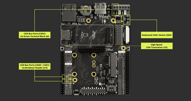
The CAN bus interface on the Portenta Mid Carrier is available through High-Density connectors. It is easily accessible via the screw terminal connectors and breakout male header provided on the carrier.
| Pin Number | Silkscreen Pin | Portenta Standard Pin | High-Density Pin | Interface |
|---|---|---|---|---|
| 26 | CAN0 TX | CAN0_TX | J1-50 | CANH |
| 28 | CAN0 RX | CAN0_RX | J1-52 | CANL |
| 30 | CAN1 TX | CAN1_TX | J1-49 | CANH |
| 32 | CAN1 RX | CAN1_RX | J1-51 | CANL |
For instance, the Portenta Mid Carrier can communicate with a Portenta Machine Control via CAN1 found within the screw terminal block. The image below shows what the connection would look like between these two devices.
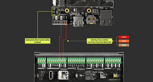
If the Breakout Header (J14) is selected as the desired port to establish CAN bus communication, the following image shows the connection example that can either use CAN0 or CAN1
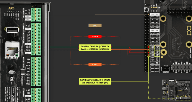
If two Portenta Mid Carriers are available, for example, and were to be used to communicate between themselves via CAN bus. The Portenta Machine Control is replaced with a Portenta Mid Carrier, which applies the same wiring setup.
Please do remember to enable the CAN1 port using the dedicated CAN1 switch (SW2) by positioning both levers to the ON state if it is to be connected via the screw terminal block (J4).
For stable CAN bus communication, it is recommended to install a 120 Ω termination resistor between CANH and CANL lines.
Using Linux
For the Portenta X8, administrative (root) privileges are preferably required to enter commands in the shell to manage the CAN bus protocol. To enable the CAN transceiver, the following command can be used:
1echo 164 > /sys/class/gpio/export && echo out > /sys/class/gpio/gpio164/direction && echo 0 > /sys/class/gpio/gpio164/valueThis sequence of commands initializes the CAN transceiver by exporting GPIO 164, configuring its direction as output, and setting its value to
LOW (0)On the Portenta X8, the following command helps verify and load the necessary CAN modules:
1sudo modprobe can-devAfter loading the
can-dev1echo "can-dev" | sudo tee > /etc/modules-load.d/can-dev.conf2sudo systemctl rebootDocker containers provide a specialized environment for command-based operations on the Portenta X8's shell, such as sending CAN frames using the cansend command:
1cansendTo send a specific CAN frame with the cansend command, the syntax is as follows:
1cansend <CAN Interface [can0 | can1]> <CAN ID>#<Data_Payload>
: Defines the CAN interface on the Portenta X8 that will be used.<CAN Interface [can0 | can1]>
: This is the message's identifier, crucial for prioritization within the network, and can be an 11-bit or 29-bit number.<CAN ID>
: The actual transmitted data can be up to 8 bytes for standard frames.<Data_Payload>
For example, to send a standard message on the
can0123DEADBEEF1cansend can0 123#DEADBEEFOr to send an extended frame with a 29-bit ID defined with
1F33445511223344556677881cansend can0 1F334455#1122334455667788The image below shows an example illustrating the Portenta X8 sending data over CAN1 to a Portenta Machine Control programmed to receive any incoming information within the CAN bus.
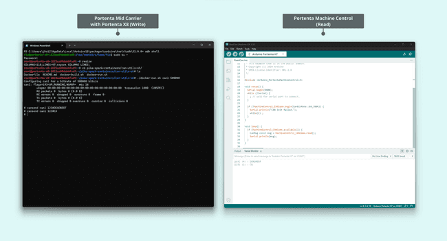
If you would like to know about using CAN bus on a Portenta Machine Control, you can check within its user manual here.
To prepare the environment for the cansend command, clone the following Docker container repository:
1git clone https://github.com/pika-spark/pika-spark-containersNavigate to the can-utils-sh directory:
1cd pika-spark-containers/can-utils-shBuild the Docker container:
1./docker-build.shRun the Docker container with the desired CAN interface and bitrate:
1sudo ./docker-run.sh can0 | can1 [bitrate]It is also possible to use the canflood script, which writes data continuously over the CAN bus. The following image shows the Portenta Mid Carrier with the Portenta X8 sending a continuous stream of data over CAN1 to a receiving Portenta Machine Control.
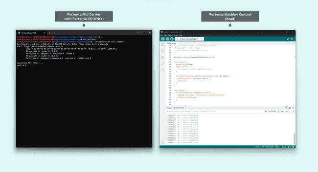
For monitoring and dumping received CAN frames, navigate to the candump directory after cloning the repository:
1cd pika-spark-containers/candumpBuild the Docker container:
1./docker-build.shRun it with the specified CAN interface and bitrate:
1sudo ./docker-run.sh can0 | can1 [bitrate]As an example, the command to start monitoring on
can0500,0001sudo ./docker-run.sh can0 500000The image below shows the Portenta X8 receiving data from a Portenta Machine Control over the CAN1 line.
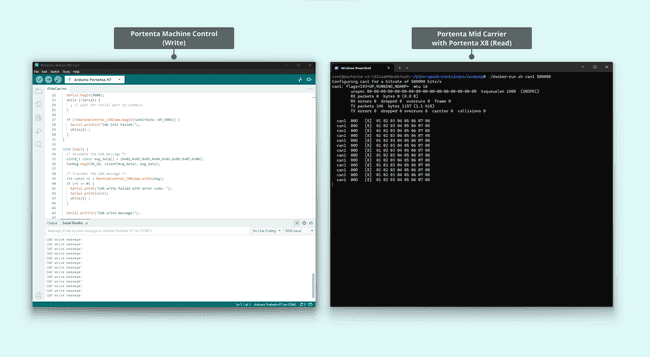
If you would like to know about using CAN bus on a Portenta Machine Control, you can check within its user manual here.
For more information regarding this container utility, please check can-utils-sh and candump.
The following are the
bustype- socketcan: Used for the SocketCAN interface native to the Linux environment.
- virtual: Establishes a virtual CAN bus for simulation or testing without physical CAN bus hardware.
- pcan: Applicable for Peak-System PCAN-USB adapters.
- canalystii: For Canalyst II CAN interface modules.
- kvaser: For interfacing with Kvaser CAN hardware.
- systec: Meant for SYS TEC electronic's CAN interfaces.
- vector: For CAN interfaces by Vector that use the XL Driver Library.
- usb2can: Compatible with 8devices' USB2CAN converter.
- ixxat: For IXXAT devices that utilize the VCI driver.
- nican: For National Instruments' range of CAN hardware.
- iscan: For Intrepid Control Systems (ICS) neoVI tools.
Each bus type aligns with a specific CAN interface or hardware type, ranging from generic Linux interfaces to proprietary devices.
Below is a Python® script that includes functions to send standard and extended CAN messages. The
main()1import can2import time3
4def send_standard_can_message(channel, message_id, data):5 msg = can.Message(arbitration_id=message_id, data=data, is_extended_id=False)6 channel.send(msg)7
8def send_extended_can_message(channel, message_id, data):9 msg = can.Message(arbitration_id=message_id, data=data, is_extended_id=True)10 channel.send(msg)11
12def main():13 # Assuming you're using a virtual channel for the CAN bus for testing.14 # If you're using real hardware like the SocketCAN interface, change 'virtual' to 'socketcan'.15 bus = can.interface.Bus(channel='virtual', bustype='virtual')16
17 while True:18 print("Sending packet ... ", end="")19 send_standard_can_message(bus, 0x12, [ord('h'), ord('e'), ord('l'), ord('l'), ord('o')])20 print("done")21
22 time.sleep(1)23
24 print("Sending extended packet ... ", end="")25 send_extended_can_message(bus, 0xabcdef, [ord('w'), ord('o'), ord('r'), ord('l'), ord('d')])26 print("done")27
28 time.sleep(1)29
30if __name__ == "__main__":31 main()The continuing script defines functions to receive and display CAN messages.
1import can2
3def receive_can_messages(bus):4 while True:5 message = bus.recv() # Blocks until a message is received6 print_received_message(message)7
8def print_received_message(message):9 print("Received ", end="")10
11 if message.is_extended_id:12 print("extended ", end="")13
14 if message.is_remote_frame:15 print("RTR ", end="")16
17 print("packet with id 0x{:X}".format(message.arbitration_id), end="")18
19 if message.is_remote_frame:20 print(" and requested length {}".format(message.dlc))21 else:22 print(" and length {}".format(len(message.data)))23
24 # Only print packet data for non-RTR packets25 for byte in message.data:26 print(chr(byte), end="")27 print()28
29 print()30
31def main():32 # Assuming you're using a virtual channel for testing.33 # If you're using real hardware like the SocketCAN interface, change 'virtual' to 'socketcan'.34 bus = can.interface.Bus(channel='virtual', bustype='virtual')35 print("CAN Receiver Callback")36 receive_can_messages(bus)37
38if __name__ == "__main__":39 main()The
main()It can also be tested with a dedicated USB stick that drives the CAN bus and connects to the Portenta Mid Carrier.
The following image resembles when it sends data from the USB CAN hosted device to the Portenta Mid Carrier.
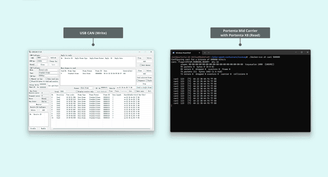
The image below resembles when data is received on the USB CAN hosted device sent from the Portenta Mid Carrier using the canflood script.
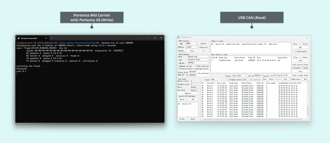
These methodologies, or setup, are helpful in debugging and analyzing the CAN bus communication between devices.
Using Arduino IDE
For Portenta C33, the following examples are provided to explore the functionality of the CAN bus protocol on Arduino IDE.
The CAN Read example tailored for Portenta C33 begins CAN communication at 500 kbps. It remains in constant vigilance for incoming messages, showing the received data as it arrives.
1#include <Arduino_CAN.h>2
3/**************************************************************************************4 * SETUP/LOOP5 **************************************************************************************/6
7void setup()8{9 Serial.begin(115200);10 while (!Serial) { }11
12 if (!CAN.begin(CanBitRate::BR_500k))13 {14 Serial.println("CAN.begin(...) failed.");15 for (;;) {}16 }17}18
19void loop()20{21 if (CAN.available())22 {23 CanMsg const msg = CAN.read();24 Serial.println(msg);25 }26}The CAN Write example, also set at 500 kbps, builds and sends a specific message format. This message includes a fixed preamble followed by an incrementing counter value that updates with each loop iteration.
1/**************************************************************************************2 * INCLUDE3 **************************************************************************************/4
5#include <Arduino_CAN.h>6
7/**************************************************************************************8 * CONSTANTS9 **************************************************************************************/10
11static uint32_t const CAN_ID = 0x20;12
13/**************************************************************************************14 * SETUP/LOOP15 **************************************************************************************/16
17void setup()18{19 Serial.begin(115200);20 while (!Serial) { }21
22 if (!CAN.begin(CanBitRate::BR_500k))23 {24 Serial.println("CAN.begin(...) failed.");25 for (;;) {}26 }27}28
29static uint32_t msg_cnt = 0;30
31void loop()32{33 /* Assemble a CAN message with the format of34 * 0xCA 0xFE 0x00 0x00 [4 byte message counter]35 */36 uint8_t const msg_data[] = {0xCA,0xFE,0,0,0,0,0,0};37 memcpy((void *)(msg_data + 4), &msg_cnt, sizeof(msg_cnt));38 CanMsg const msg(CanStandardId(CAN_ID), sizeof(msg_data), msg_data);39
40 /* Transmit the CAN message, capture and display an41 * error core in case of failure.42 */43 if (int const rc = CAN.write(msg); rc < 0)44 {45 Serial.print ("CAN.write(...) failed with error code ");46 Serial.println(rc);47 for (;;) { }48 }49
50 /* Increase the message counter. */51 msg_cnt++;52
53 /* Only send one message per second. */54 delay(1000);55}If CAN1 is the desired CAN bus port, the examples change to adapt such configurations. The example to write via CAN bus on CAN1 would be as follows:
1/**************************************************************************************2 * COMPILE TIME CHECKS3 **************************************************************************************/4
5#ifndef ARDUINO_PORTENTA_C336# error "CAN1 is only available on Portenta C33."7#endif /* ARDUINO_PORTENTA_C33 */8
9/**************************************************************************************10 * INCLUDE11 **************************************************************************************/12
13#include <Arduino_CAN.h>14
15/**************************************************************************************16 * CONSTANTS17 **************************************************************************************/18
19static uint32_t const CAN_ID = 0x20;20
21/**************************************************************************************22 * SETUP/LOOP23 **************************************************************************************/24
25void setup()26{27 Serial.begin(115200);28 while (!Serial) { }29
30 /* You need to enable the CAN transceiver31 * by commenting in below code when using32 * a Portenta H33 on a Portenta Max Carrier.33 * Note: Only CAN1 is available on the Portenta34 * Max Carrier's RJ10 CAN connector.35 */36#if (PIN_CAN1_STBY >= 0)37 pinMode(PIN_CAN1_STBY, OUTPUT);38 digitalWrite(PIN_CAN1_STBY, LOW);39#endif40
41 if (!CAN1.begin(CanBitRate::BR_500k))42 {43 Serial.println("CAN.begin(...) failed.");44 for (;;) {}45 }46}47
48static uint32_t msg_cnt = 0;49
50void loop()51{52 /* Assemble a CAN message with the format of53 * 0xCA 0xFE 0x00 0x00 [4 byte message counter]54 */55 uint8_t const msg_data[] = {0xCA,0xFE,0,0,0,0,0,0};56 memcpy((void *)(msg_data + 4), &msg_cnt, sizeof(msg_cnt));57 CanMsg const msg(CanStandardId(CAN_ID), sizeof(msg_data), msg_data);58
59 /* Transmit the CAN message, capture and display an60 * error core in case of failure.61 */62 if (int const rc = CAN1.write(msg); rc < 0)63 {64 Serial.print ("CAN.write(...) failed with error code ");65 Serial.println(rc);66 for (;;) { }67 }68
69 /* Increase the message counter. */70 msg_cnt++;71
72 /* Only send one message per second. */73 delay(1000);74}To read on the CAN1 port would be as follows:
1/**************************************************************************************2 * COMPILE TIME CHECKS3 **************************************************************************************/4
5#ifndef ARDUINO_PORTENTA_C336# error "CAN1 is only available on Portenta C33."7#endif /* ARDUINO_PORTENTA_C33 */8
9/**************************************************************************************10 * INCLUDE11 **************************************************************************************/12
13#include <Arduino_CAN.h>14
15/**************************************************************************************16 * SETUP/LOOP17 **************************************************************************************/18
19void setup()20{21 Serial.begin(115200);22 while (!Serial) { }23
24 /* You need to enable the CAN transceiver25 * by commenting in below code when using26 * a Portenta H33 on a Portenta Max Carrier.27 * Note: Only CAN1 is available on the Portenta28 * Max Carrier's RJ10 CAN connector.29 */30#if (PIN_CAN1_STBY >= 0)31 pinMode(PIN_CAN1_STBY, OUTPUT);32 digitalWrite(PIN_CAN1_STBY, LOW);33#endif34
35 if (!CAN1.begin(CanBitRate::BR_500k))36 {37 Serial.println("CAN.begin(...) failed.");38 for (;;) {}39 }40}41
42void loop()43{44 if (CAN1.available())45 {46 CanMsg const msg = CAN1.read();47 Serial.println(msg);48 }49}All these examples can be found within Arduino IDE by navigating to File -> Examples -> Arduino_CAN.
More information on using CAN bus on a Portenta Machine Control can be checked within its user manual here.
The next image shows an expected communication outcome between a Portenta Mid Carrier paired with the Portenta C33 and a Portenta Machine Control.
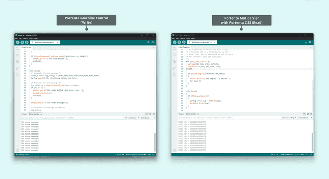
The following image shows an expected communication outcome with roles inversed between a Portenta Mid Carrier paired with the Portenta C33 and a Portenta Machine Control.
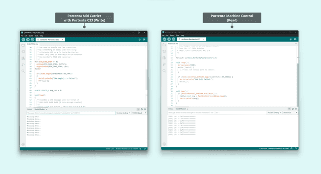
UART
The Portenta Mid Carrier supports UART communication, accommodating multiple UART interfaces. The following table outlines the available pins on the Portenta Mid Carrier designated for UART communication protocols:
| Pin Number | Silkscreen Pin | Portenta Standard Pin | High-Density Pin |
|---|---|---|---|
| 3 | RTS0 | SERIAL0_RTS | J1-38 |
| 4 | RTS1 | SERIAL1_RTS | J1-37 |
| 7 | RX0 | SERIAL0_RX | J1-36 |
| 8 | RX1 | SERIAL1_RX | J1-35 |
| 9 | TX0 | SERIAL0_TX | J1-34 |
| 10 | TX1 | SERIAL1_TX | J1-33 |
| 11 | CTS0 | SERIAL0_CTS | J1-40 |
| 12 | CTS1 | SERIAL1_CTS | J1-39 |
| 15 | RTS2 | SERIAL2_RTS | J2-30 |
| 16 | RTS3 | SERIAL3_RTS | J2-29 |
| 19 | RX2 | SERIAL2_RX | J2-28 |
| 20 | RX3 | SERIAL3_RX | J2-27 |
| 21 | TX2 | SERIAL2_TX | J2-26 |
| 22 | TX3 | SERIAL3_TX | J2-25 |
| 23 | CTS2 | SERIAL2_CTS | J2-32 |
| 24 | CTS3 | SERIAL3_CTS | J2-31 |
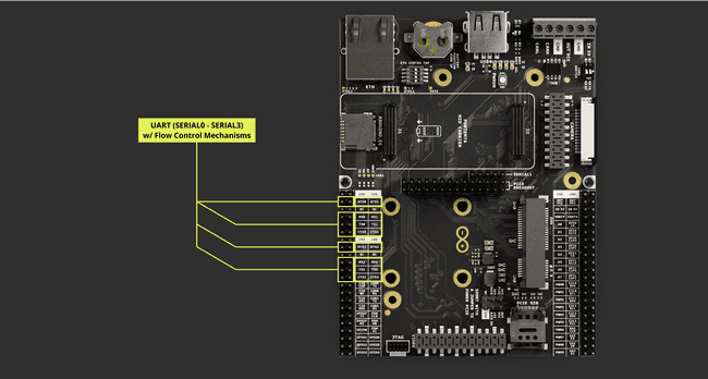
Refer to the board pinout section in the user manual for pin location. To interact with these UART pins, you can use the (Serial) library functions.
Using Linux
With root access on the Portenta X8, it is possible to list the serial ports available within Linux using the command:
1ls /dev/ttyUSB* /dev/ttyACM* /dev/ttymxc*2
3// Similar to following4/dev/ttyUSB0 /dev/ttyUSB2 /dev/ttymxc1 /dev/ttymxc35/dev/ttyUSB1 /dev/ttyUSB3 /dev/ttymxc2Typical serial devices might be listed as /dev/ttyUSBx, /dev/ttyACMx, or /dev/ttymxcx, with an example output being /dev/ttymxc2.
The Python® script below demonstrates how to employ the pyserial library for UART communication. The processData function is defined to handle the incoming data, which you can customize for your specific application.
1import serial2import time3
4# Define the processData function (you'll need to fill this in based on your requirements)5def processData(data):6 print("Received:", data) # For now, just print the data. Modify as needed.7
8# Set up the serial port9ser = serial.Serial('/dev/ttymxc2', 9600) # Use the appropriate port and baud rate for your device10
11incoming = ""12
13while True:14 # Check for available data and read individual characters15 while ser.in_waiting:16 c = ser.read().decode('utf-8') # Read a single character and decode from bytes to string17
18 # Check if the character is a newline (line-ending)19 if c == '\n':20 # Process the received data21 processData(incoming)22
23 # Clear the incoming data string for the next message24 incoming = ""25 else:26 # Add the character to the incoming data string27 incoming += c28
29 time.sleep(0.002) # Delay for data buffering, equivalent to Arduino's delay(2);This script maintains a serial connection on port /dev/ttymxc2 with a baud rate of 9600. It reads incoming data character by character until a newline (
\nAfter processing the data, it resets in preparation for the next message. The
time.sleep(0.002)delay(2);Using Arduino IDE
The examples provided below show UART communication for using Portenta H7 or C33. Establishing the baud rate (bits per second) in the
setup()1// Start UART communication at 9600 baud2Serial.begin(9600);The
Serial1.available()Serial1.read()while()When a character indicating the end of a line is detected, the following code segment processes and compiles the received characters into a String variable:
1void loop() {2 while (Serial1.available()) {3 delay(2);4 char c = Serial1.read();5 if (c == '\n') {6 processData(incoming);7 incoming = "";8 } else {9 incoming += c;10 }11 }12}13
14void processData(String data) {15 Serial.println("Received: " + data); // Print on Serial Monitor16}Consequently, the following provides a complete example illustrating the reception of incoming data via UART:
1String incoming = "";2
3void setup() {4 Serial1.begin(9600); // For communication with Arduino using RX1 and TX15 Serial.begin(9600); // For debugging over USB6}7
8void loop() {9 while (Serial1.available()) {10 delay(2);11 char c = Serial1.read();12 if (c == '\n') {13 processData(incoming);14 incoming = "";15 } else {16 incoming += c;17 }18 }19}20
21void processData(String data) {22 Serial.println("Received: " + data); // Print on Serial Monitor23}To ease data transmission over UART, which can complement the receiving board as depicted above, consider the example below:
1void setup() {2 Serial1.begin(9600);3}4
5void loop() {6 Serial1.println("Hello from Portenta!");7 delay(1000);8}By using these codes, you will notice the message
"Hello from Portenta!"The
Serial.write()1// Transmit the string "Hello world!2Serial.write("Hello world!");The example code above dispatches the string
"Hello world!"Serial.write()To transmit strings through UART, the following methods can be used:
1// Transmit the string "Hello world!"2Serial.print("Hello world!");3
4// Transmit the string "Hello world!" followed by a newline character5Serial.println("Hello world!");The key difference is that
Serial.println()\nSerial.print()So, using the example provided above for the Portenta X8 and assigning the Portenta H7, each attached to the Portenta Mid Carrier, the result may look as follows:
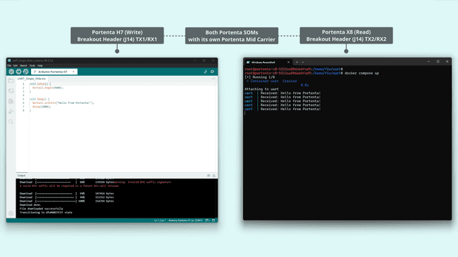
Support
If you encounter any issues or have questions while working with the Portenta Mid Carrier, we provide various support resources to help you find answers and solutions.
Help Center
Explore our Help Center, which offers a comprehensive collection of articles and guides for the Portenta Mid Carrier. The Arduino Help Center is designed to provide in-depth technical assistance and help you make the most of your device.
Forum
Join our community forum to connect with other Portenta Mid Carrier users, share your experiences, and ask questions. The forum is an excellent place to learn from others, discuss issues, and discover new ideas and projects related to the Portenta Mid Carrier.
Contact Us
Please get in touch with our support team if you need personalized assistance or have questions not covered by the help and support resources described before. We're happy to help you with any issues or inquiries about the Portenta Mid Carrier.
Suggest changes
The content on docs.arduino.cc is facilitated through a public GitHub repository. If you see anything wrong, you can edit this page here.
License
The Arduino documentation is licensed under the Creative Commons Attribution-Share Alike 4.0 license.