Connecting Two Nano 33 IoT Boards Through UART
Learn how to send data from a Nano 33 IoT board to another board via UART.
In this tutorial we will control the built-in LED on the Arduino Nano 33 IoT from another Arduino Nano 33 IoT. To do so, we will connect both boards using a wired communication protocol called UART.
Note: This example would work connecting an Arduino Nano board with any other Arduino board, but be mindful that both board must work at the same voltage. If the operating voltage differ between connected boards, the board with the lower operating voltage could be damaged.
In this example, we will power both the Arduino boards through the computer, then we will use the Serial Monitor to send some commands to the Nano 33 IoT board, that will be connected through the UART with another Nano 33 IoT board. Depending on the commands received by the Nano 33 IoT board, it will turn ON or OFF its built-in LED.
Goals
The goals of this project are:
- Understand what the UART is.
- Use UART communication between two Arduino boards.
Hardware & Software Needed
For this project we will need:
- Arduino Nano 33 IoT
- Arduino Nano 33 IoT (or any other Arduino board that works at 3.3V)
- 2 x mini breadboard
- 3 x jumper wires
UART Communication
UART (Universal Asynchronous Receiver-Transmitter) is one of the most used device-to-device communication protocols. It allows an asynchronous serial communication in which the data format and transmission speed are configurable. The UART communication sends data bits one by one, from the least significant to the most significant, framed by start and stop bits so that precise timing is handled by the communication channel.
Embedded systems, microcontrollers, and computers mostly use UART as a form of device-to-device hardware protocol. Among the available communication protocols, UART uses only two wires for its transmitting and receiving ends, TX (Transmitter) and RX (Receiver). These pins are dedicated for that specific purpose, either transmitting or receiving.
Asynchronous means there is no clock signal to synchronize the output bits from the transmitting device going to the receiving end, but the baud rate needs to be the same on both the transmitting and receiving devices. The baud rate, is the rate at which information is transferred to a communication channel. In the serial port context, the set baud rate will serve as the maximum number of bits per second to be transferred.
UART is the communication protocol we use to communicate the PC to the board through the USB cable. In some older boards, TX and RX pins are used for communication with the computer, which means connecting anything to these pins can interfere with that communication, including causing failed uploads to the board. This is not the case for the Nano or MKR families, since these ones have two separate channels, using Serial for the communication with the computer and Serial1 for the communication with any other device through UART.
If you want to learn more about the UART protocol and how it works, you can check this link.
Circuit
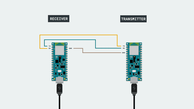
In order to communicate both Arduino boards, we will need to connect them as shown in the image below.

At the moment of making the connections, we need to remember that this protocol has two dedicated lines TX and RX so we need to make sure to connect the TX pin, of one of the boards, with the RX of the other one. The same goes for the second, where his TX pin need to be connected to the RX pin of the first board.
To finish, it is very important that we connect the GND pins of both boards to each other. If we don't do this, the voltage reference will be different for each one of the boards so the communication won't work as intended.
Note: In order to enable serial communication, both Arduino boards must be connected to your computer via USB.
Creating the Program
1. Configuring the Receiver board
First, let's connect the Arduino Nano 33 IoT board to the computer and opening the Arduino Web Editor. This board will act as the receiver, which means that it will only receive data from the other board and turn ON or OFF the built-in LED according the received values. To start with the programming, start a new sketch and name it Nano_UART_receiver.
1.1. Receiver code walkthrough
Let's start inside the
setup()OUTPUTSerial1.begin()1void setup() {2 pinMode(LED_BUILTIN, OUTPUT); // set LED pin as output3 digitalWrite(LED_BUILTIN, LOW); // switch off LED pin4
5 Serial1.begin(9600); // initialize UART with baud rate of 96006}Note: If you want to initialize the UART communication with any other Arduino board, please check here the serial port and the pins you need to use.
Inside the
loop()Serial1.available()whilewhile() receivedDataSerial1.read()1void loop() {2 while (Serial1.available() >= 0) {3 char receivedData = Serial1.read(); // read one byte from serial buffer and save to receivedDataNow, we need to add a
if...else'1''0'Note: When we use UART communication, all the data transmitted is text formatted, which means that we need to use character logic instead of numeric logic for compatibility. For example, in order to know if the data received is a "5" we need to check with the ASCII character of 5 ('5') instead of the numeric value of 5 (5). Therefore, we use dataReceived == '5' instead of dataReceived == 5.
1if (receivedData == '1') {2 digitalWrite(LED_BUILTIN, HIGH); // switch LED On3 }4 else if (receivedData == '0') {5 digitalWrite(LED_BUILTIN, LOW); // switch LED Off6 }7 }8}1.2. Uploading the code to the receiver
Once we have finished the code, let's upload it to our Arduino Nano 33 IoT board. This board is now programmed to act as the receiver in this scenario. Once the code is uploaded, let's connect the other board to the computer.
Note: After uploading the code to the receiver board, it is not necessary for it to stay connected to the computer in order to function. However, it needs to be powered in order to work.
2. Configuring the Transmitter board
It is time to open a new sketch and name it as Nano_UART_transmitter, then let's start initializing the built in LED and the Serial communication as we did in the previous code but in this case since we need to read data also from the Serial Monitor we need to initialize the serial communication with the computer adding a
Serial.begin()1void setup() {2 pinMode(LED_BUILTIN, OUTPUT); // set LED pin as output3 digitalWrite(LED_BUILTIN, LOW); // switch off LED pin4
5 Serial.begin(9600); // initialize serial communication at 9600 bits per second:6 Serial1.begin(9600); // initialize UART with baud rate of 96007}In the
loop()if1Serial1.println()digitalWrite()Serial.println1void loop() {2 if (Serial.read() == '1'){3 Serial1.println('1');4 digitalWrite(LED_BUILTIN, HIGH);5 Serial.println("LEDS ON");6 }Then, using an
else if01else if (Serial.read() == '0'){2 Serial1.println('0');3 digitalWrite(LED_BUILTIN, LOW);4 Serial.print("LEDS OFF");5 }6}2.1 Uploading the code to the transmitter
Once we have finished the code, let's upload it to our other Arduino Nano 33 IoT board. This board is now programmed to act as the transmitter.
3. Complete code
If you choose to skip the code building section, the complete code for both the receiver and the transmitter can be found below:
Receiver:
1void setup() {2 pinMode(LED_BUILTIN, OUTPUT); // set LED pin as output3 digitalWrite(LED_BUILTIN, LOW); // switch off LED pin4
5 Serial1.begin(9600); // initialize UART with baud rate of 96006}7void loop() {8 while (Serial1.available() >= 0) {9 char receivedData = Serial1.read(); // read one byte from serial buffer and save to receivedData10 if (receivedData == '1') {11 digitalWrite(LED_BUILTIN, HIGH); // switch LED On12 }13 else if (receivedData == '0') {14 digitalWrite(LED_BUILTIN, LOW); // switch LED Off15 }16 }17}Transmitter:
1void setup() {2 pinMode(LED_BUILTIN, OUTPUT); // set LED pin as output3 digitalWrite(LED_BUILTIN, LOW); // switch off LED pin4
5 Serial.begin(9600); // initialize serial communication at 9600 bits per second:6 Serial1.begin(9600); // initialize UART with baud rate of 96007}8void loop() {9 if (Serial.read() == '1'){10 Serial1.println('1');11 digitalWrite(LED_BUILTIN, HIGH);12 Serial.println("LEDS ON");13 }14 else if (Serial.read() == '0'){15 Serial1.println('0');16 digitalWrite(LED_BUILTIN, LOW);17 Serial.print("LEDS OFF");18 }19}Testing It Out
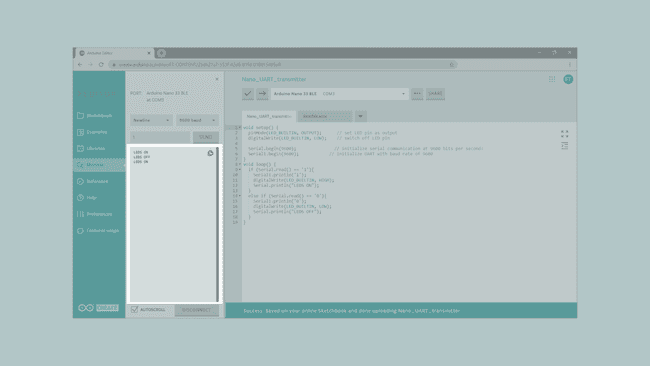
After you have successfully verified and uploaded the sketch to the two boards, make sure the transmitter board is connected and open the Serial Monitor. You need to enter a 1 to turn ON both LEDs, or a 0 to turn them OFF.

Troubleshoot
Sometimes errors occur, if the code is not working there are some common issues we can troubleshoot:
- Missing a bracket or a semicolon.
- Arduino board connected to the wrong port.
- Connection between the Arduino boards are not correct.
- Accidental interruption of cable connection.
Conclusion
In this simple tutorial we learned how to connect two Arduino boards so that they can communicate using UART communication.
Suggest changes
The content on docs.arduino.cc is facilitated through a public GitHub repository. If you see anything wrong, you can edit this page here.
License
The Arduino documentation is licensed under the Creative Commons Attribution-Share Alike 4.0 license.